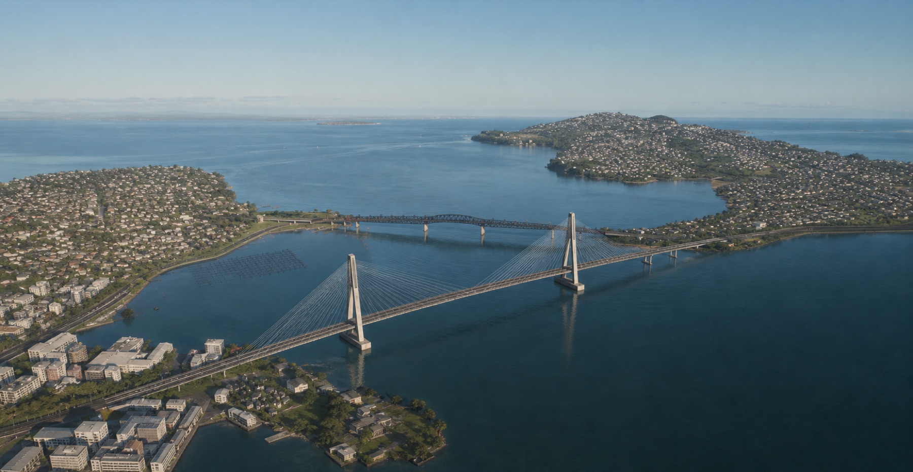
Waitematā Crossing · Field Study 01
The bridge model exposed a path conflict and produced a ten-sheet record for specialist review.
A 3.0 metre path reduced to 2.2 metres, five corrected defects and seven open holds
Detailing the stay anchorage exposed a material coordination problem: the first arrangement reduced the walking and cycling path from 3.0 metres to 2.2 metres. The model and drawing review made that conflict visible before the study advanced.
The study began with Nicolas Reid's May 2026 public proposal for a second Waitematā crossing. It developed the proposal's corridor and operating intent into a coordination model, two structural options and a ten-sheet stay anchorage package.
Revision P02 corrected five P01 defects, replaced an unsupported fatigue pass with a hold and carries seven open anchorage questions. The next test is whether a bridge specialist can continue a design change from that record. The package is preliminary and is not for construction or fabrication.
- Alignment
- 2,000 m800 m main span
- Deck
- 38.0 mtraffic, transit, walking, cycling
- Anchorages
- 256modelled housings
- Sheets
- 10ST-0600 to ST-0609
- Open holds
- 7H1 to H7
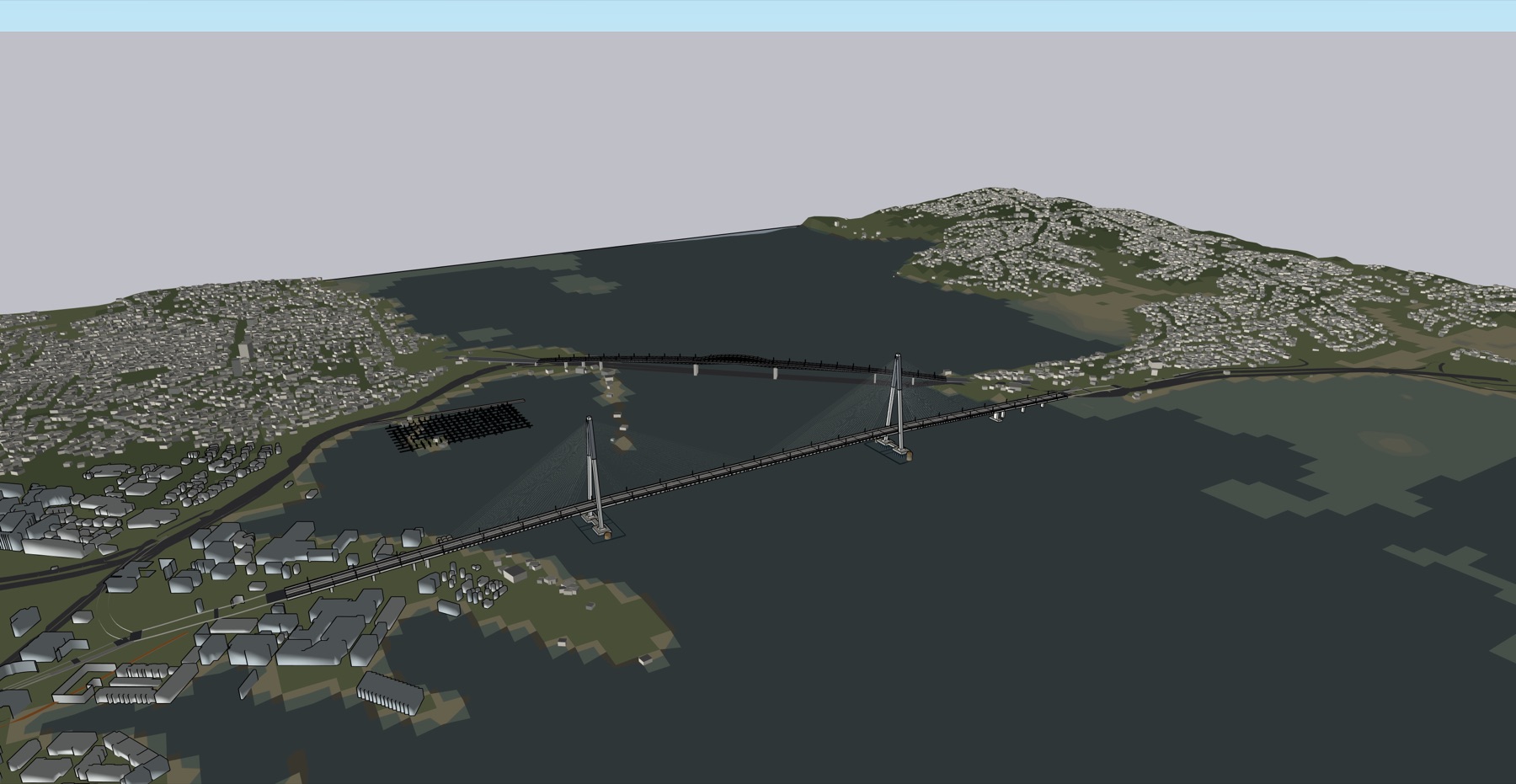
The model develops Landform's bridge geometry within the proposal's corridor and operating intent.
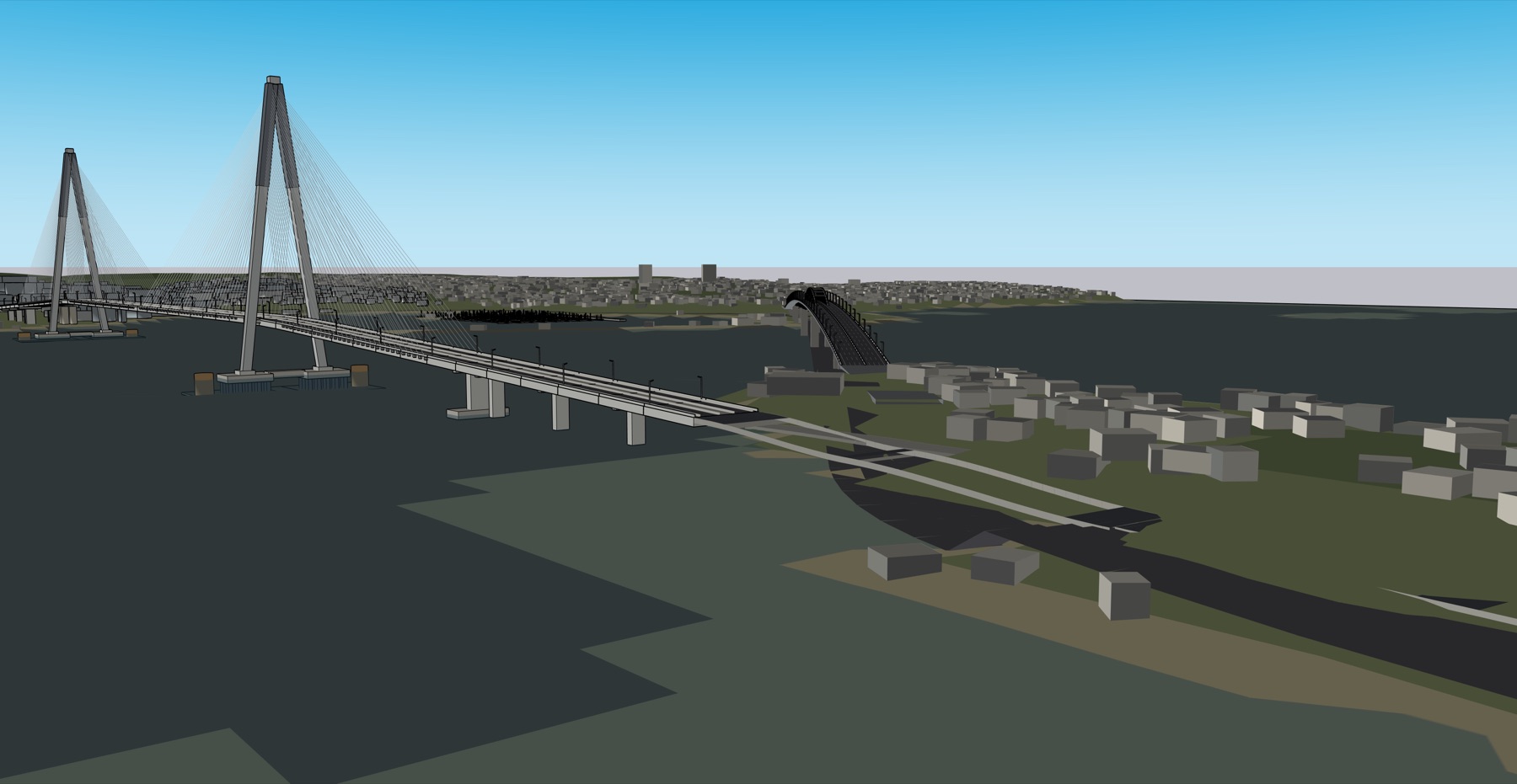
The proposal describes a multimodal bridge just east of the existing crossing, running from the Onewa interchange to the Victoria Park viaduct. It would carry southbound motorway lanes, two-way rapid transit and paths for walking and cycling, with the existing bridge working alongside it as one system.
Those inputs establish the form and operating intent. The table separates the published proposal from the geometry developed for this study.
Several parts of the proposal remain outside the model: the two-bridges-as-one-system operating allocation, Te Onewa station, and the Westhaven and St Marys Bay outcomes. The current model carries two lanes each way; the proposal assigns four southbound motorway lanes to the new bridge.
- Corridor
- Onewa to the Victoria Park viaduct, east of the existing bridge. Both tie-ins are represented in the harbour context model.
- Length
- Proposal 1,800 to 2,000 m. Model 2,000 m: 800 m main span, 350 m side spans, 250 m approaches.
- Deck
- Proposal around 38 m, multimodal. Model 38.0 m carrying walking, cycling, transit and traffic.
- Clearance
- Proposal 43 m, matching the existing bridge. Model 43.0 m held over a 500 m navigation channel.
- Structure
- Proposal cable-stayed. Model Option A cable-stayed, with Option B tied arch tested as a comparator.
- Landform additions
- The 800 m main span and the A-frame towers are design developments, not prescribed by the proposal.
Source: Greater Auckland, "Build this brilliant bridge", 27 May 2026
Named inputs connect the source material to the model, calculations, drawings and review record.
One SketchUp file contains the harbour context, both structural options and the anchorage detail.
The coordination model is a single SketchUp file, waitemata_
The context is open data. Ground comes from the LINZ one metre elevation model, the seabed from LINZ hydrographic soundings merged into the same surface, and the surrounding city from OpenStreetMap building footprints with heights taken from tags where they exist.
The context exposed an early placement error. The existing harbour bridge was first placed from a geocoded position and ended in mid-air over deep water. Its abutments were then re-derived from the ground surface at the tightest crossing recorded by the elevation model. Later coordination depends on both structures meeting the recorded terrain.
- Model file
- waitemata_
crossing_ city_ context_ P02.skp - Contents
- 798 groups, 165,795 faces, 21 tags, 16 scenes
- Ground
- LINZ 1 m elevation model, Auckland 2024
- Seabed
- LINZ hydrographic soundings, inverse-distance merged
- City
- OpenStreetMap footprints, heights from tags where present
- Water depth on the alignment
- About 15 m at the north tower, 6 m at the south
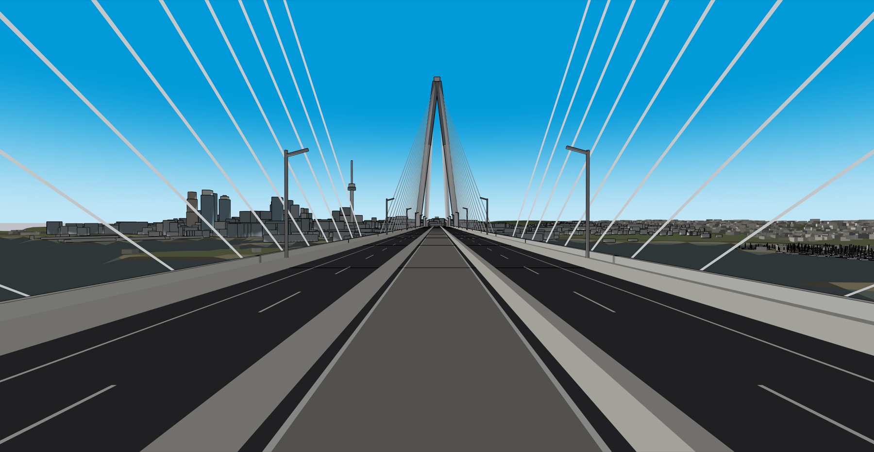
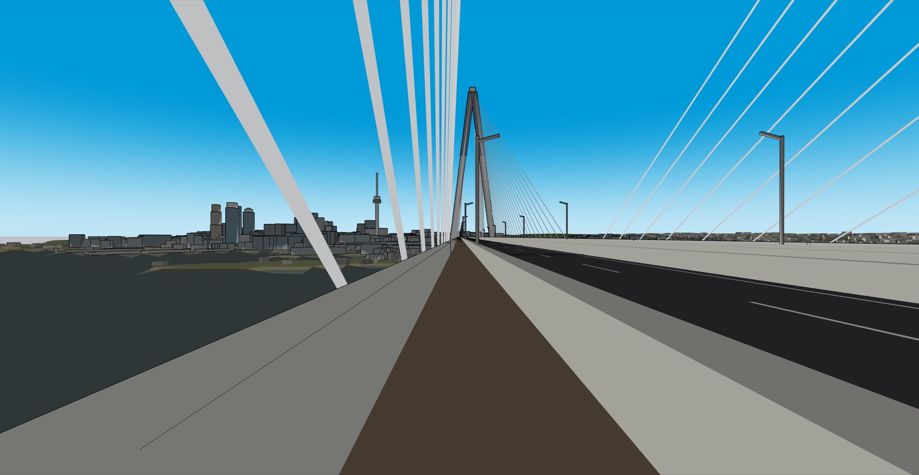
Option A advanced to anchorage detailing. Option B remains held on its erection method.
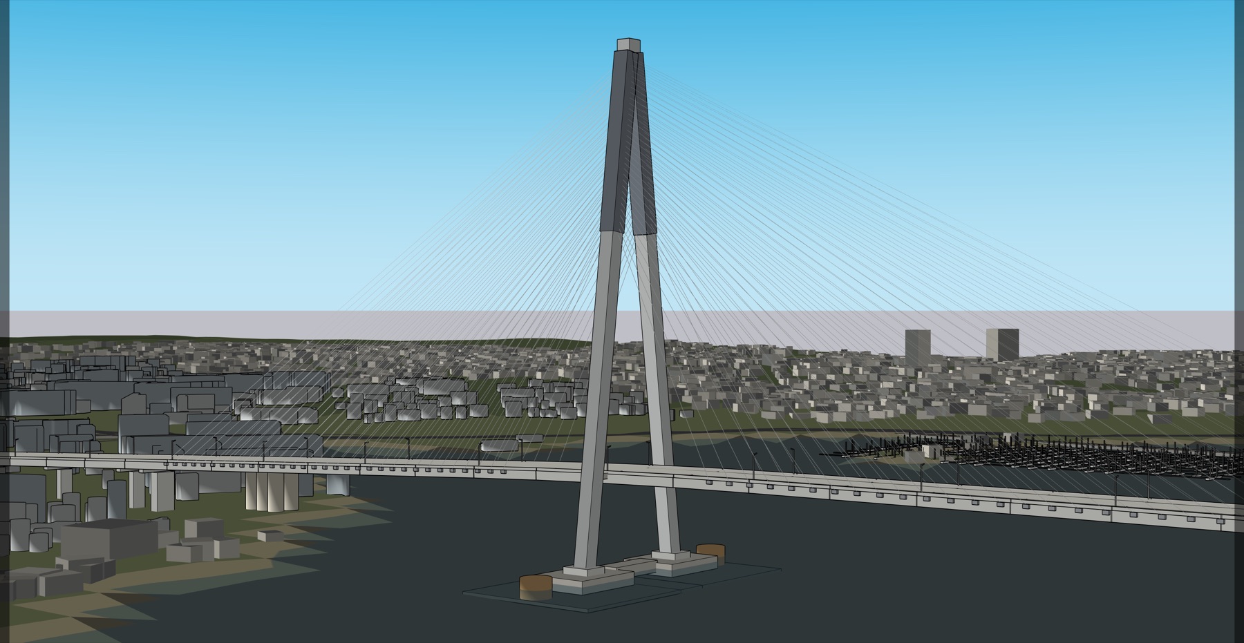
Option A develops the proposal's cable-stayed form: an 800 metre main span between twin A-frame towers, 350 metre side spans with anchor piers, and 250 metre approaches. It is the option carried into the detail package.
Option B is a half-through tied steel truss arch of 550 metres, tested as a comparator on the same deck. Its preliminary screens report a total horizontal thrust of 344.4 MN, 172.2 MN per rib, 32.4 metre hanger spacing and 62 strand hangers, with in-plane utilisation 0.663, out-of-plane 0.858 and pattern-load beam-column interaction 0.81.
Option B passed 69 of 70 checks in the current consistency screen. The unresolved check is the half-arch erection method, so the option remains a comparator and did not advance to detailing.
The two options are mutually exclusive alternatives on one corridor. They are shown here as separate figures with a matched camera, never combined into a single scene.
| Quantity | Option A | Option B |
|---|---|---|
| Form | Cable-stayed | Half-through tied arch |
| Main span | 800 m | 550 m |
| Deck | 38.0 m | 38.0 m |
| Clearance | 43.0 m | 43.0 m |
| Status | Developed to detailP02 | Comparison only |
| Blocking item | Seven anchorage holds | Erection method |
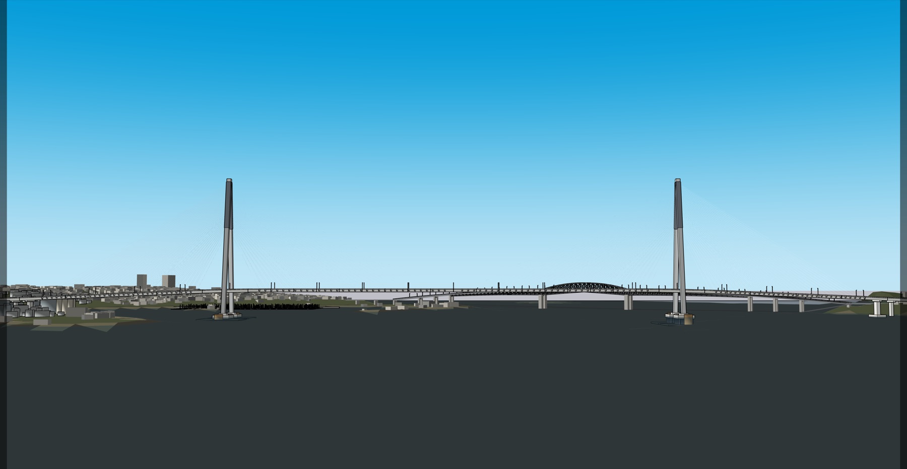
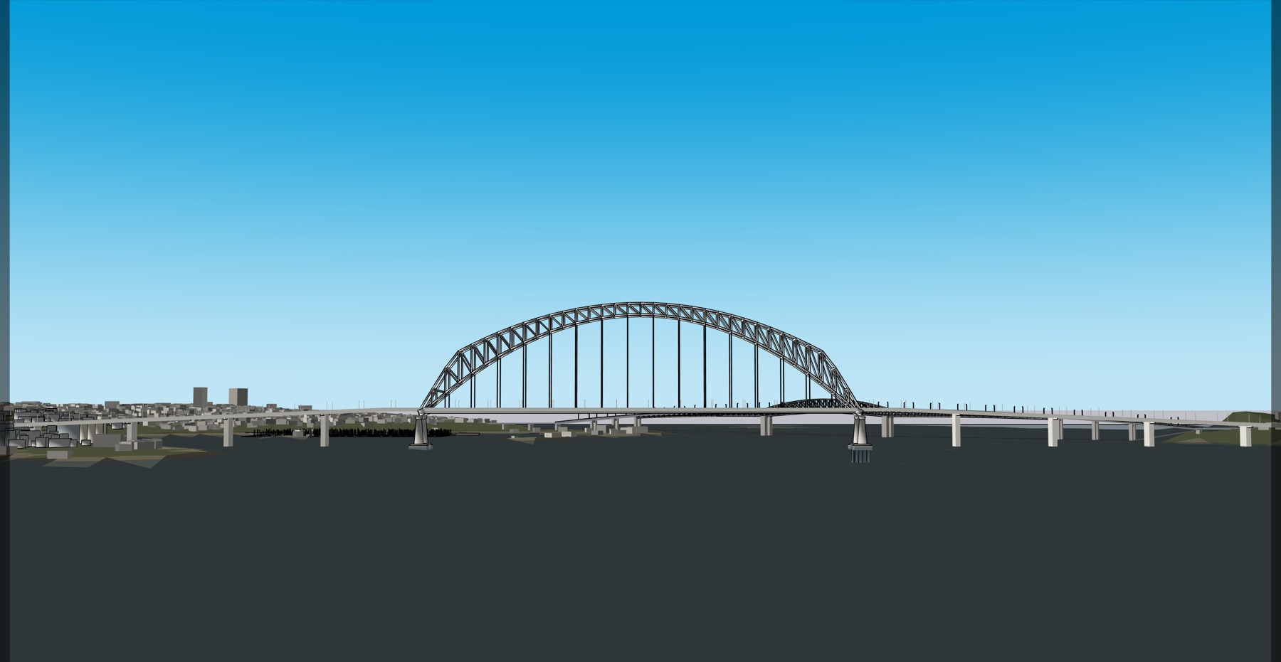
The first anchorage arrangement reduced the three-metre walking and cycling path to 2.2 metres.
The model originally carried a blister anchorage: a raised anchor block on the deck plate, with the stay entering above the running surface. The arrangement occupied part of the declared three-metre active path, leaving 2.2 metres clear at each of the 32 positions per face.
Detailing exposed a coordination defect that was not visible in the general arrangement.
Four families of stay-to-deck anchorage were compared. The external node outboard of the deck edge was developed, with the edge girder and transverse diaphragm retained as the fallback.
Family D was selected to keep the path clear and support replacement. Its structural efficiency has not been established, and family C has more precedent. No built example of an outboard anchorage on a bridge of this class was identified in the sources reviewed, so acceptance remains hold H1. If H1 cannot be closed, the package reverts to family C and the continuous active path is lost.
| Family | Argument for | Argument against |
|---|---|---|
| A · anchor box inside the girder | Short direct load path, protected, deck clear | Confined stressing; fatigue-critical region inside primary structure |
| B · blister on the deck top | Simplest fabrication, fully accessible | Occupies the deck surface; leaves 2.2 m of a 3.0 m path |
| C · edge girder with diaphragm | Deck surface clear; substantial precedent | Fatigue-critical welded attachment; access still internal |
| D · external node outboarddeveloped | Path continuous at every position; anchor reachable and replaceable | Adds torsion and eccentric transfer needing 3D proof; no built precedent identified in reviewed sources |
- Reference stay
- BACK-01, 73 strands
- Preliminary SLS demand
- 8.242 MN against a 9.165 MN threshold at 45% GUTS, ratio 0.899
- Preliminary ULS demand
- 11.319 MN against a 13.239 MN threshold at 65% GUTS, ratio 0.855
- Cable GUTS
- 20.367 MN. The anchorage must transmit this, not the design force
- Stay inclination at deck
- 30.6 degrees
- Back and main fan pitch
- 8,387 mm and 10,484 mm
- Assemblies
- 2 towers × 2 fans × 32 positions × 2 deck edges = 256
- Provisional plan gap
- 0.30 m between the path outer face and the node inner face
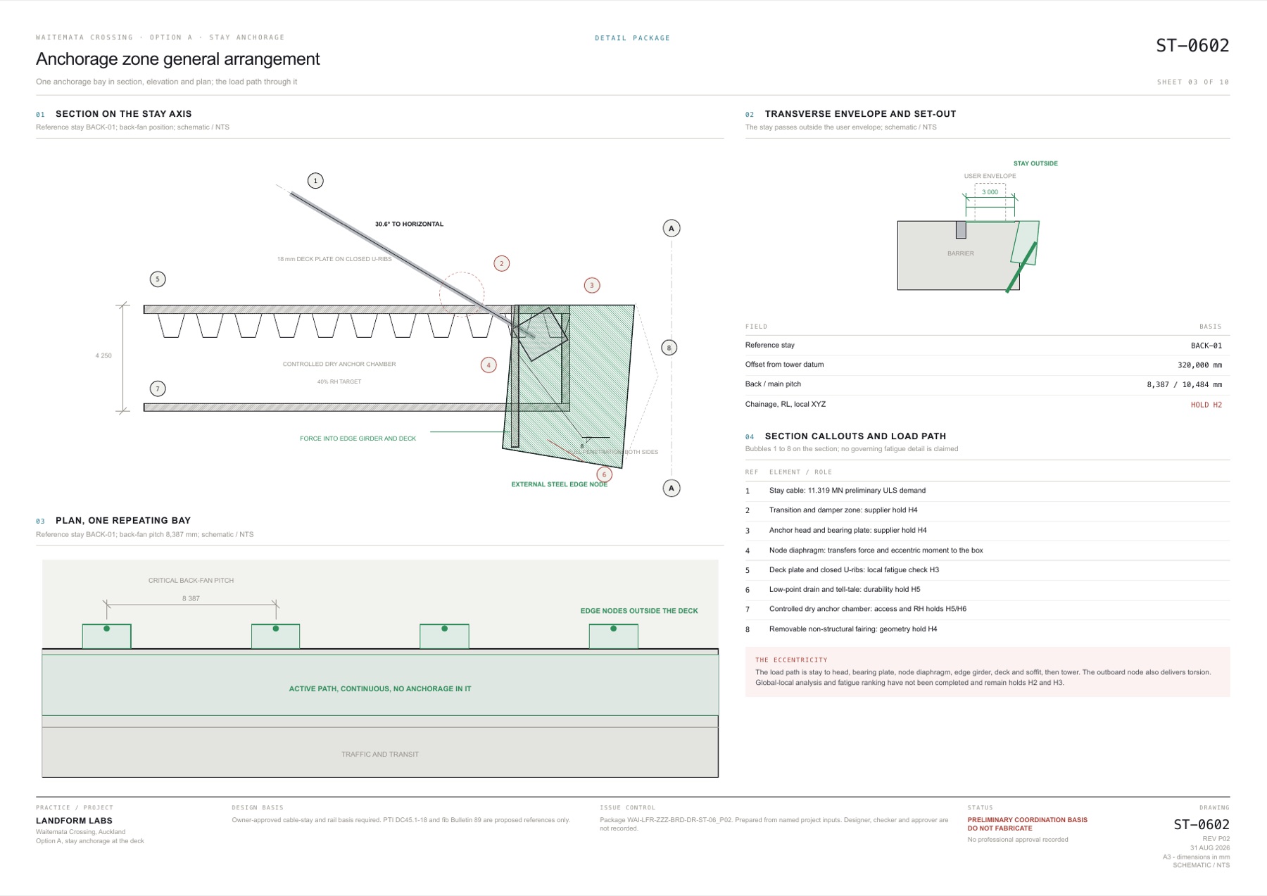
The ten-sheet package records the anchorage decision, supporting evidence and seven open holds.
Package WAI-LFR-ZZZ-BRD-DR-ST-06 revision P02 contains ten A3 sheets. Each one carries a decision, the evidence behind it and the hold that remains. The set is a preliminary coordination basis and is stamped do not fabricate, with no designer, checker or approver recorded.
The first sheet states the governance position. The NZTA Bridge Manual excludes cable-stayed bridges and railway loading, so a project-specific cable-stay and rail design basis, documented departures and special studies would all be required. The structure would be managed as a Category 1 structure under the Highway Structures Design Guide, including a wholly independent design review.
Sources are graded on each sheet: E1 for primary or official material, E2 for secondary or inferred, E3 for assumption. Supplier geometry sits at E2, because no stay system has been selected and two published bearing plates differ by 35 millimetres in diameter, which alone changes the node end diaphragm.
- ST-0600
- Package contents and design basis
- ST-0601
- Anchorage typology and selection
- ST-0602
- Anchorage zone general arrangement
- ST-0603
- Edge node plate layout, P1 to P7
- ST-0604
- Weld map and fatigue detail categories, W1 to W7
- ST-0605
- Anchor head and supplier envelope
- ST-0606
- Corrosion, drainage and dehumidification
- ST-0607
- Stressing, replacement and access
- ST-0608
- Tolerances and shop first-article test
- ST-0609
- References, hold points and verification
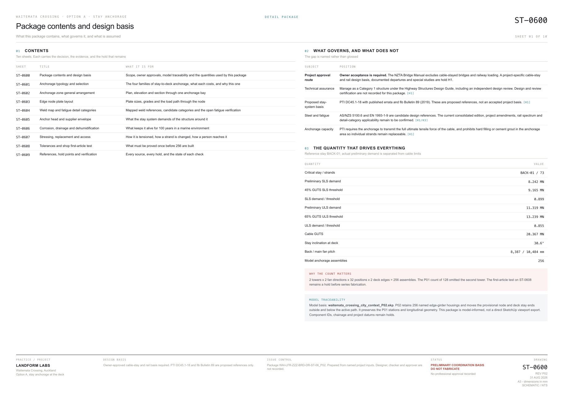
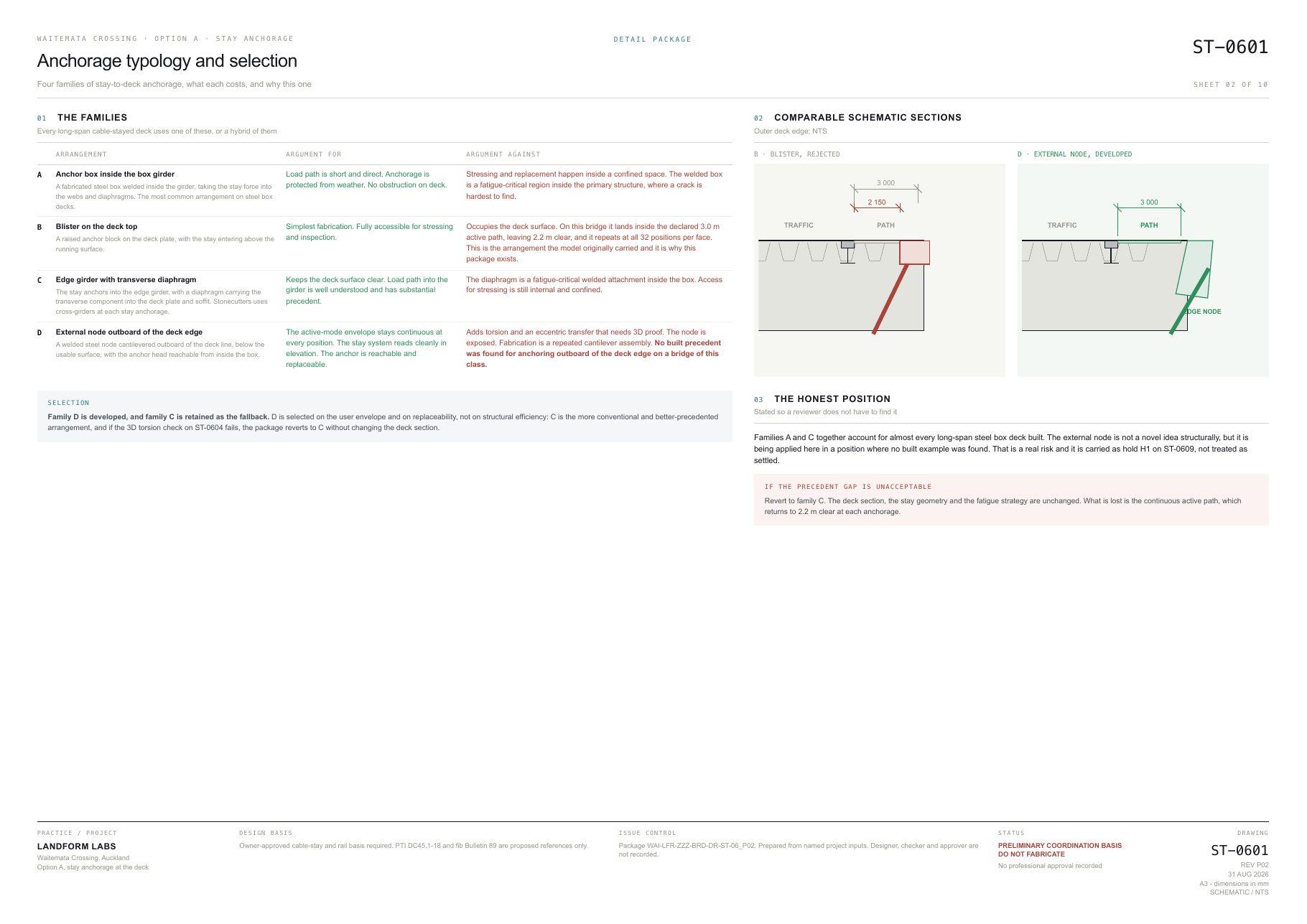
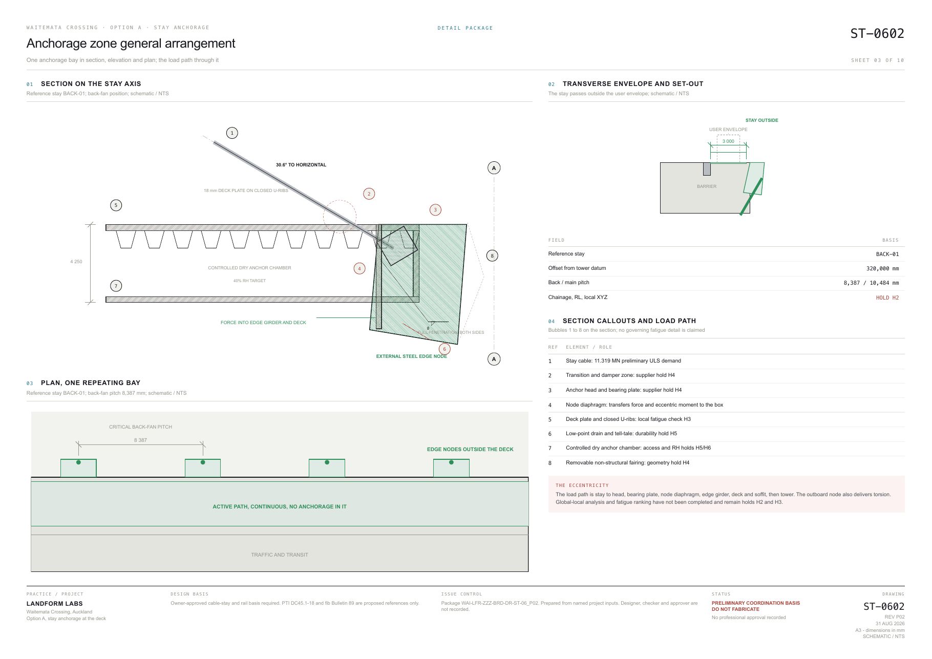
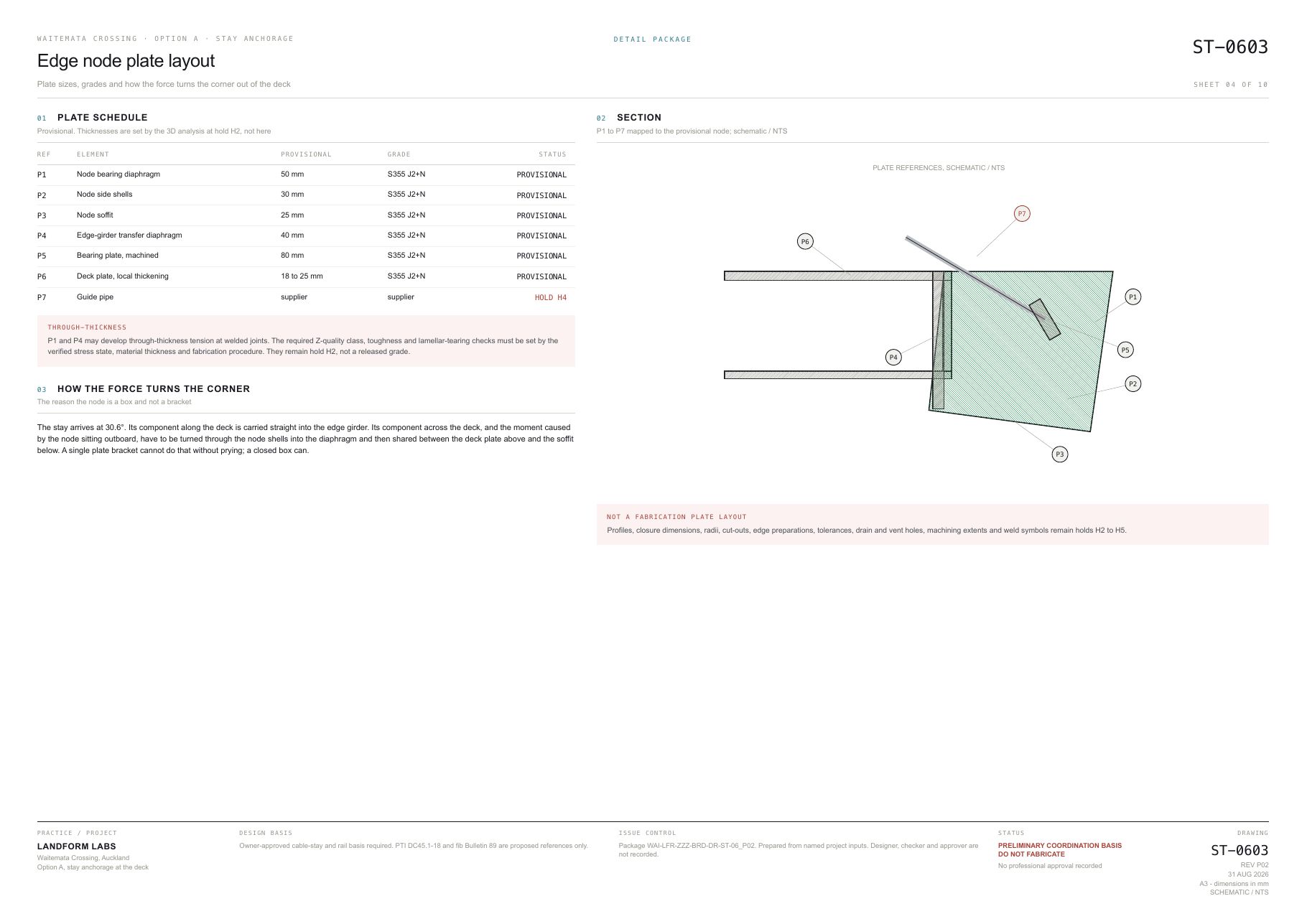
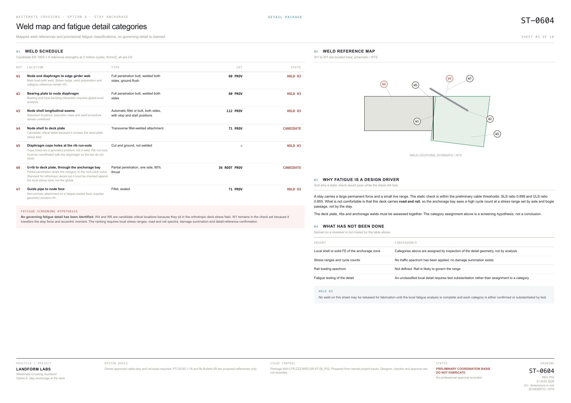
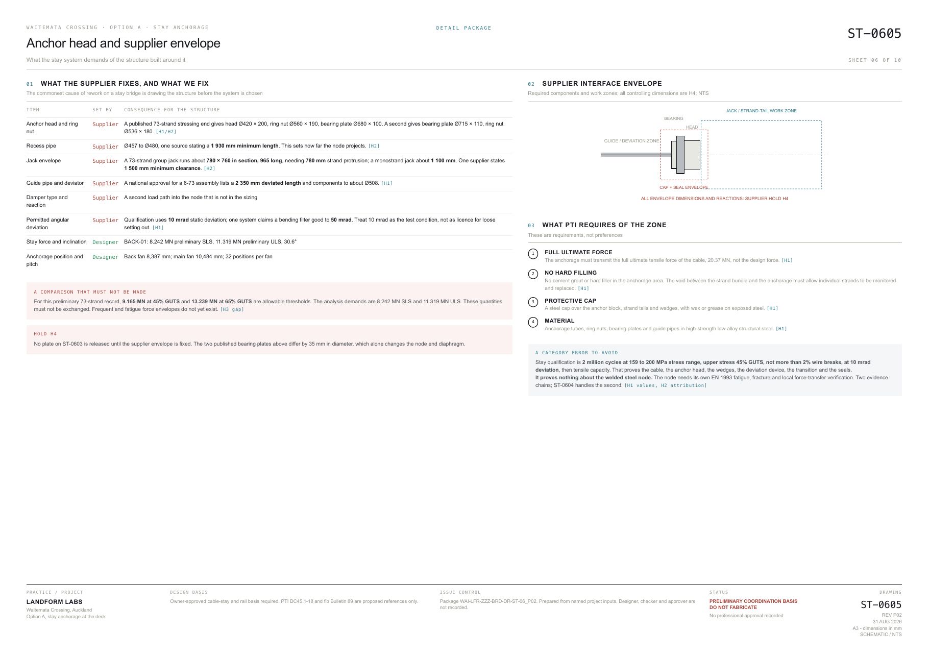
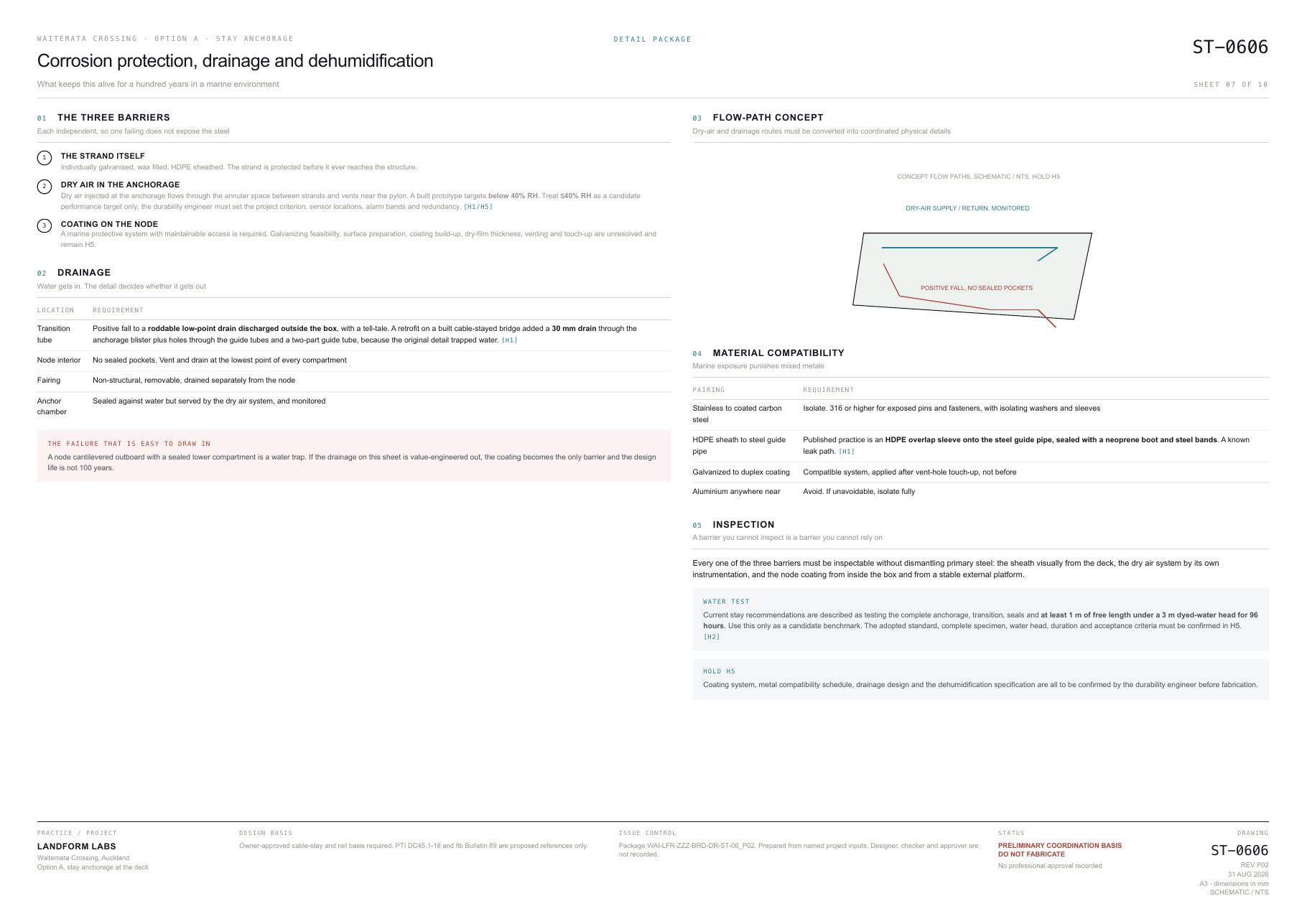
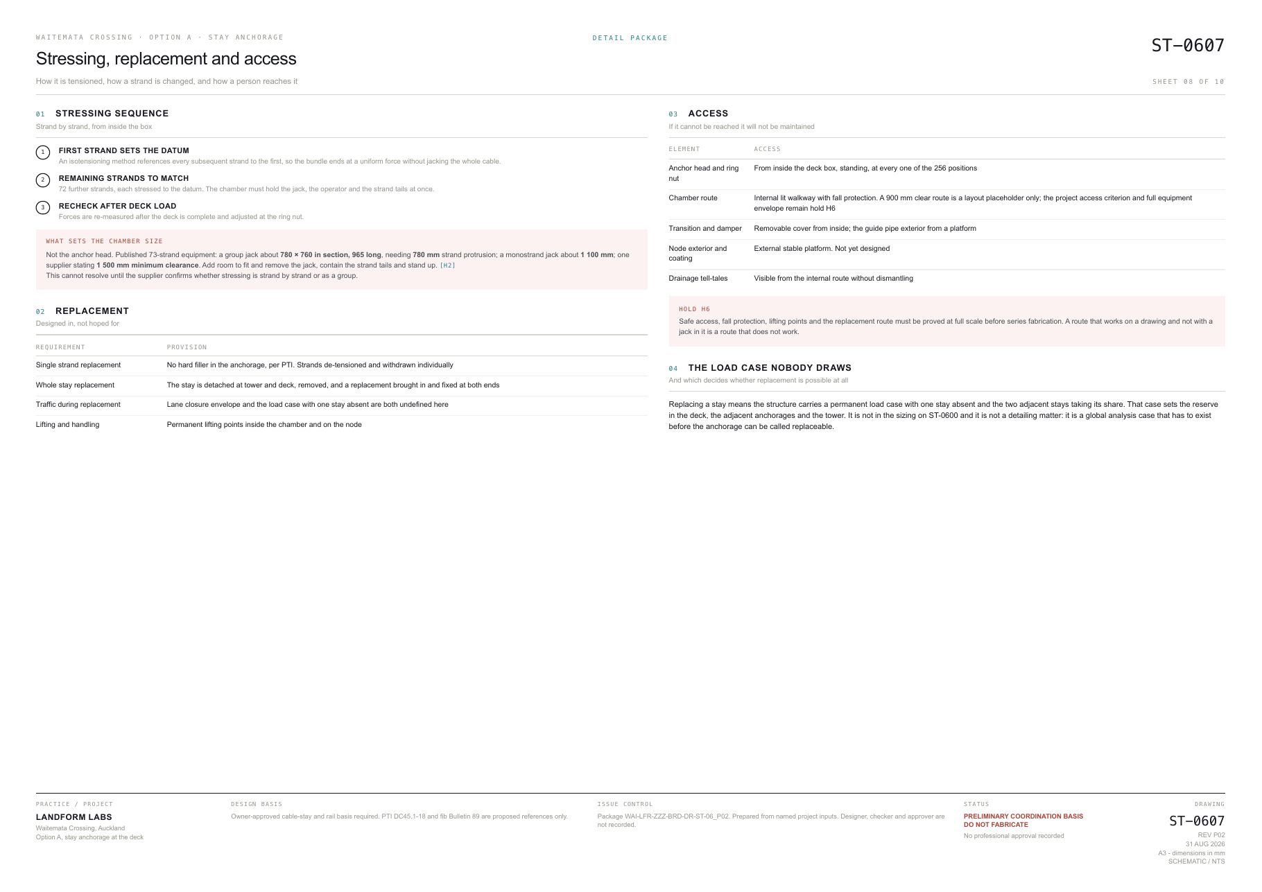
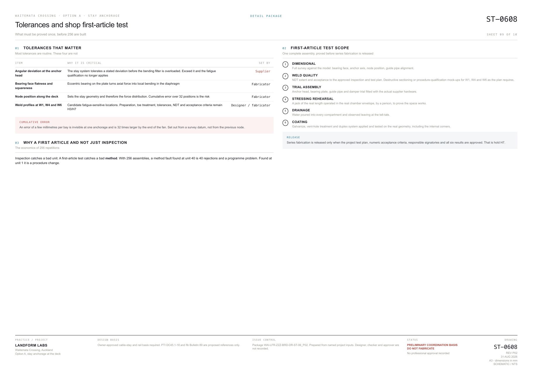
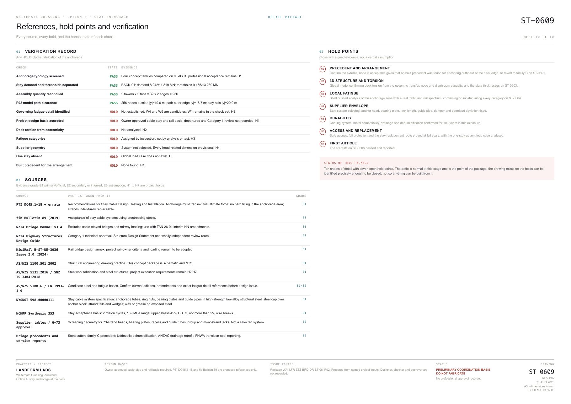
Ten A3 sheets, package WAI-LFR-ZZZ-BRD-DR-ST-06 revision P02, 31 August 2026. Preliminary coordination basis. Do not fabricate.
P02 corrected five P01 defects and replaced the unsupported fatigue pass with hold H3.
Revision P01 received a structured review. P02 records a response to each of six findings: five changes to the model or document and one withdrawn claim.
The register lists ten sheets. The document contains nine.
Document integrityST-0607 rendered as a header only and ST-0608 was nested on the same page. P02 contains ten separate A3 sheets.
The assembly count omits the second tower.
128 corrected to 256Two towers, two fan directions, 32 positions and two deck edges give 256 assemblies. P01 had counted 128. The quantity affects the first-article requirement and fabrication planning.
Demand and capacity are being quoted as if they were the same class of number.
Quantities separatedPreliminary demand, allowable thresholds and the cable breaking force are now stated separately and labelled. They must not be exchanged.
One pitch is quoted for two different fans.
8,387 and 10,484 mmBack-fan and main-fan spacing are reported separately.
The anchorage extends 0.85 m into the walking and cycling path.
Path clearance restoredP02 moves the housing outside the three-metre path and records a provisional 0.30 m plan gap in both the model and the drawings. Supplier confirmation remains open.
Fatigue is written as a pass. It has not been analysed.
Claim withdrawn, hold openedNo governing fatigue detail has been identified. The categories on ST-0604 are a screening hypothesis assigned by inspection of the detail geometry, and they are now labelled as such under hold H3.
External validation found a separate defect in the coordinate frame. An earlier frame was left-handed, so every three-dimensional view mirrored Auckland in plan: the existing harbour bridge appeared east of the new alignment when it is west. Three adversarial review cycles and the automated checks missed the error because each relied on the same internal frame. Comparison with external ground truth exposed it. The frame was corrected and the model rebuilt.
The consistency screen has a clear limit: it tests agreement with the project's selected ranges. Design adequacy and external ground truth require separate checks.
P02 records four passed checks and seven open holds against named evidence.
Source: ST-0609, package revision P02
Seven holds define the evidence needed before the anchorage can advance.
The ten-sheet package records seven holds for this anchorage detail and remains marked Do not fabricate. Each hold names the evidence required for closure. Wider transport, global structural, foundation, geotechnical, wind, seismic, vessel impact and owner approval questions sit outside the package's scope.
H1
Precedent and arrangementConfirm the external node is acceptable given that no built precedent was identified in the sources reviewed, or revert to family C.
H2
3D structure and torsionA global model confirming deck torsion from the eccentric transfer, node and diaphragm capacity, and the plate thicknesses on ST-0603.
H3
Local fatigueShell or solid analysis of the anchorage zone with a real traffic and rail spectrum, confirming or substantiating every weld category.
H4
Supplier envelopeStay system selected, with anchor head, bearing plate, jack length, guide pipe, damper and permitted deviation fixed.
H5
DurabilityCoating system, metal compatibility, drainage and dehumidification confirmed for one hundred years in this exposure.
H6
Access and replacementSafe access, fall protection and the stay replacement route proved at full scale, with the one-stay-absent load case analysed.
H7
First articleThe six tests on ST-0608 passed and reported before series fabrication of 256 assemblies is released.
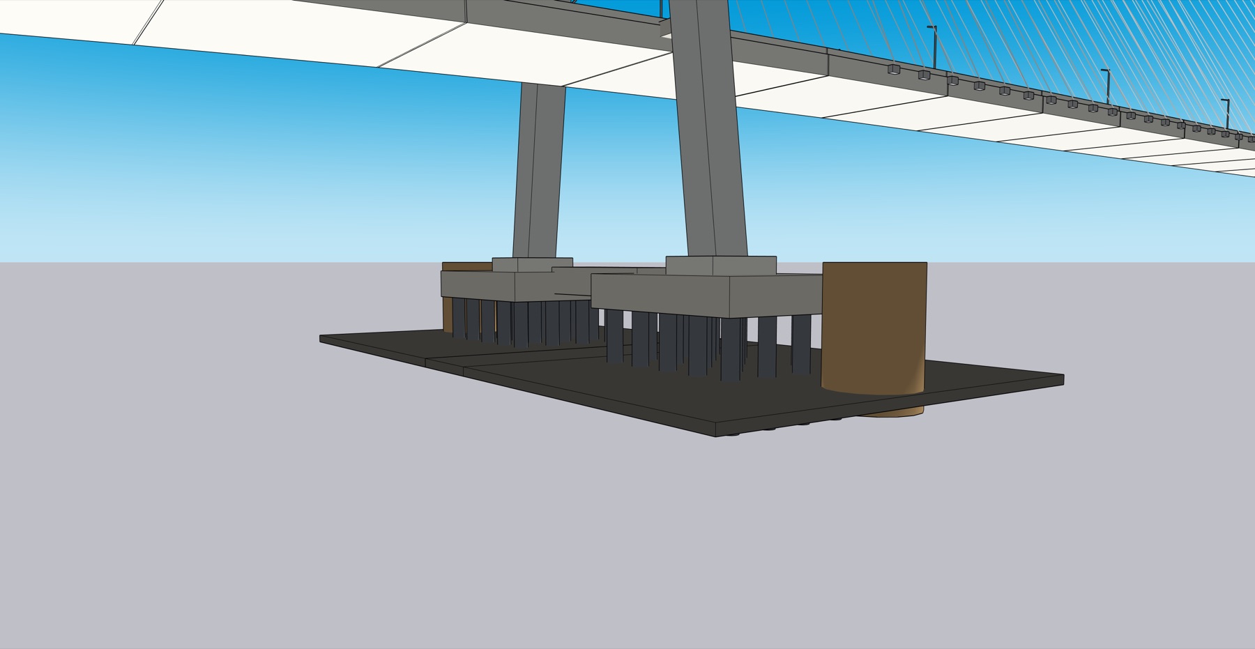
The workflow produced model and drawing revisions. Assessing their technical adequacy still requires a bridge specialist.
The workflow produced the model, drawings and revision record. Assessing evidence, technical gaps and option credibility requires bridge-engineering knowledge I do not have. Every technical output therefore needs specialist review.
It linked sources to named inputs, rebuilt geometry after input changes and maintained a clear sequence of next actions. No conventional baseline was recorded for time, cost or review effort, so the study makes no productivity claim.
The next test should be run with bridge specialists, using a firm's own project records, reference details and design criteria. It will examine whether specialist decisions remain connected to the evidence and generated outputs.
Workflow contribution
Assembled sources, linked them to named inputs, rebuilt geometry, generated drawings and ran the screen.
Human decisions
I set the brief, chose the option, assessed every finding and decided which conclusions the package supported.
Specialist work still required
Structural verification, precedent confirmation, supplier selection, specialist design and professional approval.
Not measured
No conventional baseline has been recorded for time, cost or review effort. No productivity claim is made.
The package is partly traceable and reviewable. Specialist handover remains untested.
The study produced an anchorage package and a record of its corrections. Bridge-wide continuity and independent specialist handover remain untested. One generalist operator ran the study using public-source information, with no project surveys, no multidisciplinary coordination, no independent specialist review and no professional approval.
The next stage will test whether a bridge specialist can work in the early model while its evidence, assumptions, revisions, drawings and unresolved questions remain connected to each decision. This study does not demonstrate autonomous design, compliance, certification or measured productivity.
Handover will be tested by asking a specialist to change the named parameters, regenerate the model and drawings, and update the affected holds without reconstructing the project history.
- Traceable
- Partial
- Coherent
- Partial
- Reviewable
- Partial
- Ready to continue
- Untested
Boundary. Independent concept study. Preliminary coordination basis only. No professional design, check, certification or approval is recorded. Geometric coordination is not structural acceptance. Not for construction or fabrication. All seven anchorage holds remain open.
Both issued documents are available with their open holds intact.
The field study is a nine-page account of the work. The anchorage package is its ten-sheet technical record. Both are published unchanged from their issued versions, including the holds printed on the sheets.
Preliminary coordination basis. Do not fabricate.
The related studies
The same workflow has been run at other scales: a hut on Aotea Great Barrier Island, a land-bank listing at Massey read against the plan in force, and a consented townhouse site at Paparangi. Why the work is shared this way covers the reasoning behind publishing the review record alongside the output.