Aotea Hut · Great Barrier Island
Testing what AI can do with a land listing, open data and human review.
How AI helped gather site evidence, test two options, and prepare a package for review
I used a Trade Me listing, open site data and a reference board to test how AI could support an early design study for a hut on Aotea.
Over four hours, the study moved from the listing for 24.3 hectares of bush on Aotea Great Barrier Island to a LiDAR siting analysis, two schemes modelled on the chosen pad, an early detail package for specialist review, a cost range with sourced rates, and this page.
AI helped resolve the title, assemble the terrain, run the analysis, build the model, prepare the drawings and price the early options. I set the brief, chose the direction and reviewed each output. The 28 changes below show how the design developed through that process.
- Elapsed
- ~4 hrsone working session
- Corrections
- 28review decisions
- Terrain
- 62,646faces from 1 m LiDAR
- Renders
- 1375 to 180 s each
- Cost rates
- 31sourced + confidence tagged
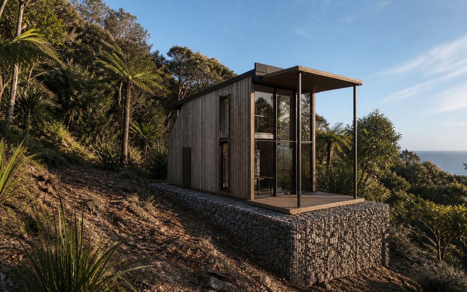
Site information, modelling and review moved together through one repeatable workflow.
The study began with the land, its constraints and the questions still unanswered.
"SE63/NW62 Rosalie Bay Road" is a parish allotment reference rather than a street address. A search of the LINZ parcel data connected it to two legal parcels on one title, then to the LiDAR coverage for the site.
The ground model used two public one-metre LiDAR tiles from LINZ. They were combined and clipped to the title and its immediate surroundings, creating matching views of the ground and tree canopy.
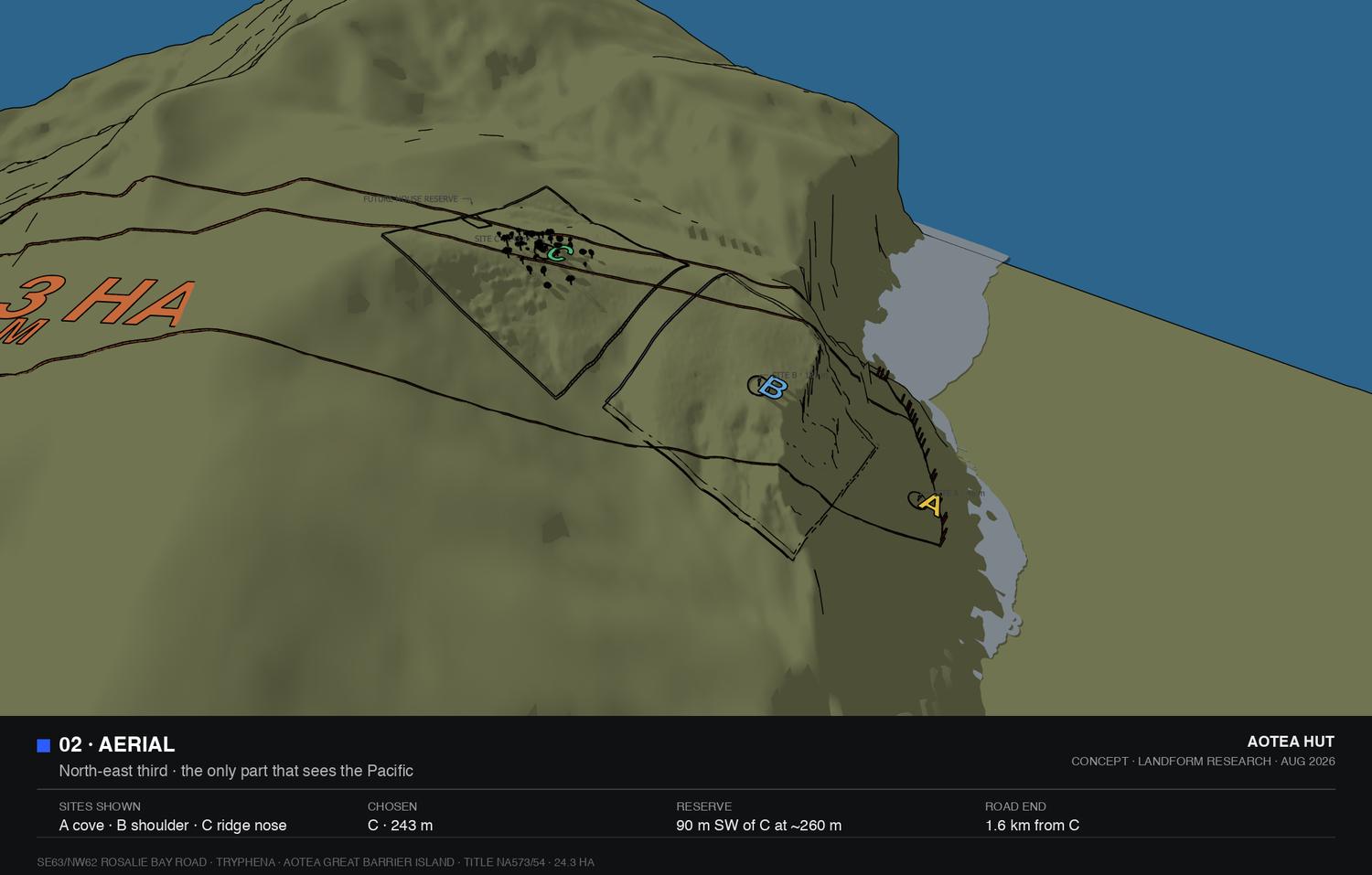
The siting study compared slope, canopy height, shelter, walking distance and the likely sea view from a 12 metre building pad. The detailed calculation sampled the horizon every five degrees out to 1.5 kilometres, then combined the five measures into one comparison score.
- Title
- Allot NW62 + SE63 PSH of Aotea, NA573/54
- Rasters
- DEM + DSM, 1 m, 1978 × 1590 px
- Tiles
- AZ34_10000_0105, AZ35_10000_0101
- Libraries
- rasterio, numpy, scipy, shapely, pyproj
- Outputs
- 7 analysis rasters, 3 candidate pads
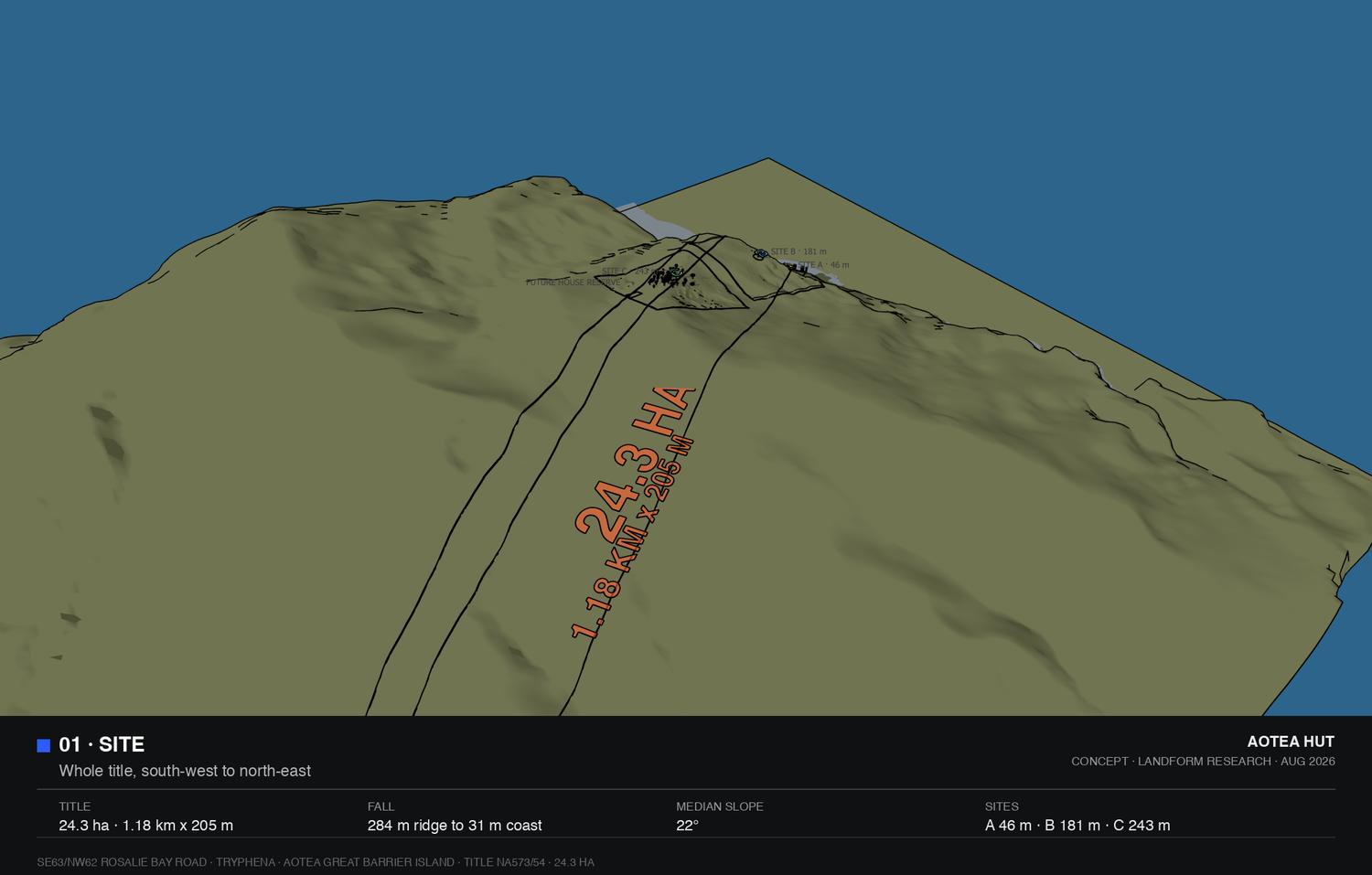
Three possible building areas made the site trade-offs visible.
The first five panels describe the site. The sixth compares them, but only where the average slope across a 12 metre building pad falls below 16 degrees. On this title that leaves a narrow ribbon through the middle of the block, and the blank ground either side of it runs between 25 and 35 degrees.
The remaining layers pull against each other. Sea view, measured as openness through the north-east to south-east sector with canopy blocking applied, is strongest in the upper two thirds. Shelter from the prevailing south-west runs the other way and peaks at the low coastal end. Canopy height sits between 5 and 15 metres almost everywhere, so any pad implies clearing, and the walk in from the end of Rosalie Bay Road runs from 1.6 to 2.0 kilometres.
The analysis selected one strong candidate at each elevation: a coastal terrace, a mid-slope shoulder and a ridge top. This produced three genuinely different positions to compare, rather than three neighbouring points on the same shoulder.
| Candidate | Score | Slope | Sea view | Shelter | Canopy | Walk in |
|---|---|---|---|---|---|---|
| A · coastal terrace 46 m | 0.58 | 14.7° | 0.40 | 0.99 | 10.5 m | 1,953 m |
| B · mid-slope shoulder 181 m | 0.81 | 11.1° | 1.00 | 0.65 | 7.5 m | 1,821 m |
| C · ridge topchosen 243 m | 0.84 | 12.7° | 1.00 | 0.57 | 2.8 m | 1,608 m |
C gives up much of the shelter A offers. In exchange it takes the open view, the shortest walk, and 2.8 metres of canopy instead of 10.5, which is the difference between trimming a clearing and felling one.
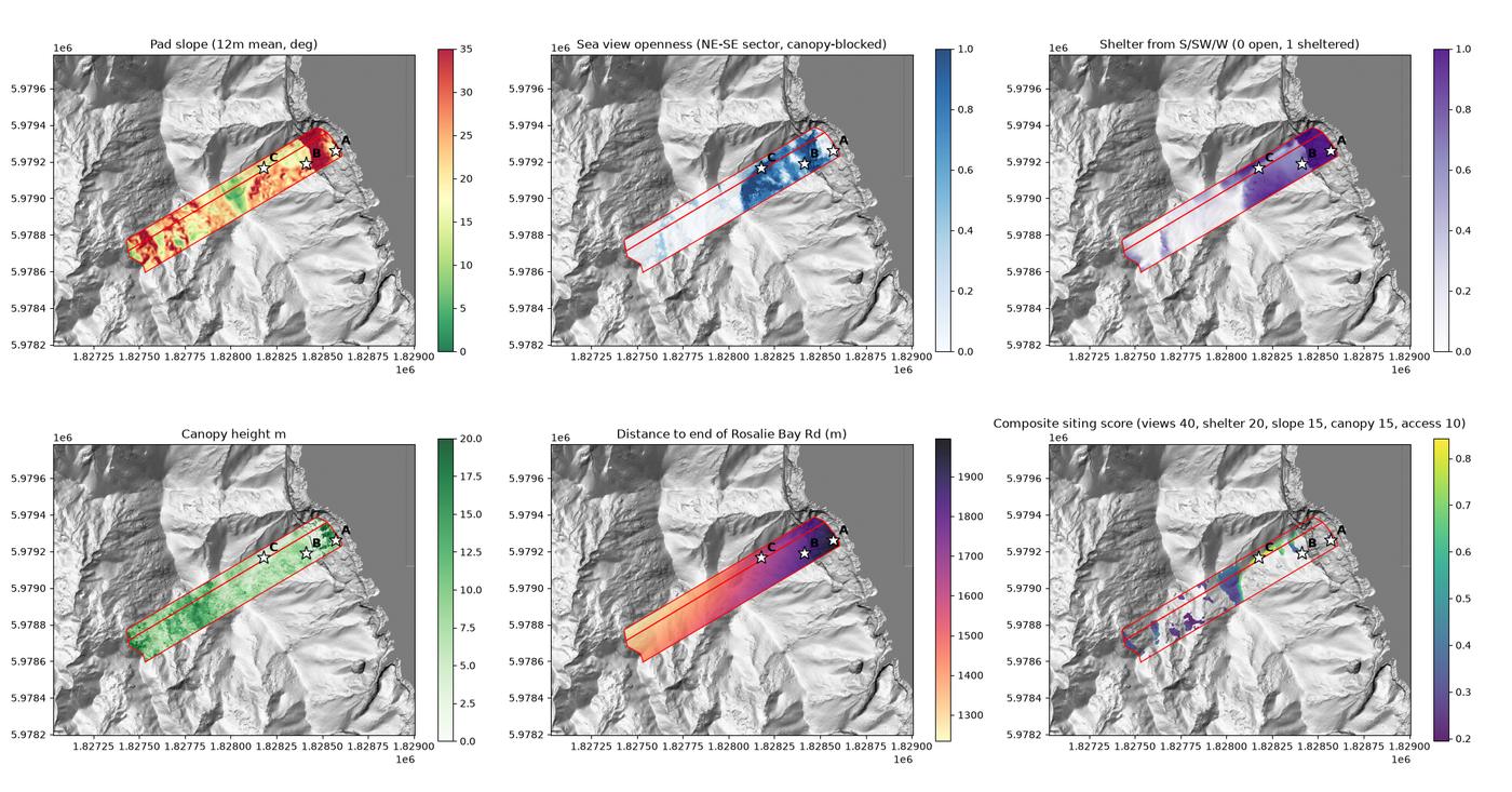
A repeatable SketchUp model made each design change quicker to test.
The terrain and both hut options were built directly inside SketchUp from a set of repeatable instructions. The technical connection used an open-source extension and generated Ruby, but the practical benefit was simple: the model could be rebuilt after each review.
Changes such as "make the deck wrap all four sides" or "raise the awning so it clears the eyeline" could be applied to the model and checked again in about a minute. The same model exports the drawing views, the CAD handoff, the web geometry and the render cameras, so all four move together.
The process also exposed three practical rules: the API works in inches while the builders write millimetres, never cut an opening through a wall with a push-pull because it silently deletes the wall, and never place anything on terrain with a raycast, because it hits canopies and roofs. Heights come from the elevation model directly.
- Transport
- TCP socket, localhost, JSON frames
- Command
- eval_ruby, generated per operation
- Terrain
- 10 m context mesh, 2 m patches at the pads
- Builders
- 2 huts, ~50 named parts each
- Scenes
- 12 curated, tag state bound per scene
- Exports
- glTF, DWG, DXF, PNG, PDF
Open the model behind the study.
The SketchUp file includes the LiDAR terrain, both hut options and the 12 curated scenes used through the study. It is shared for inspection as concept work, not for construction. Dimensions and site information require independent verification.
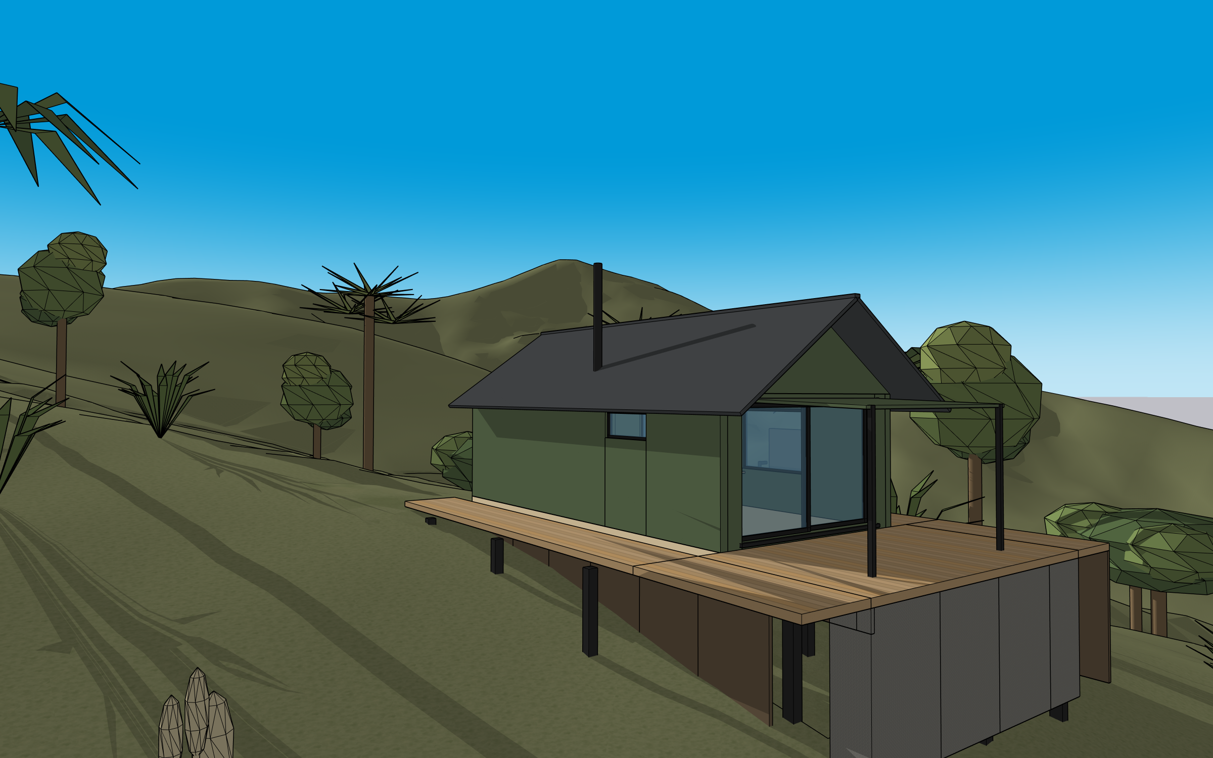 Model
Model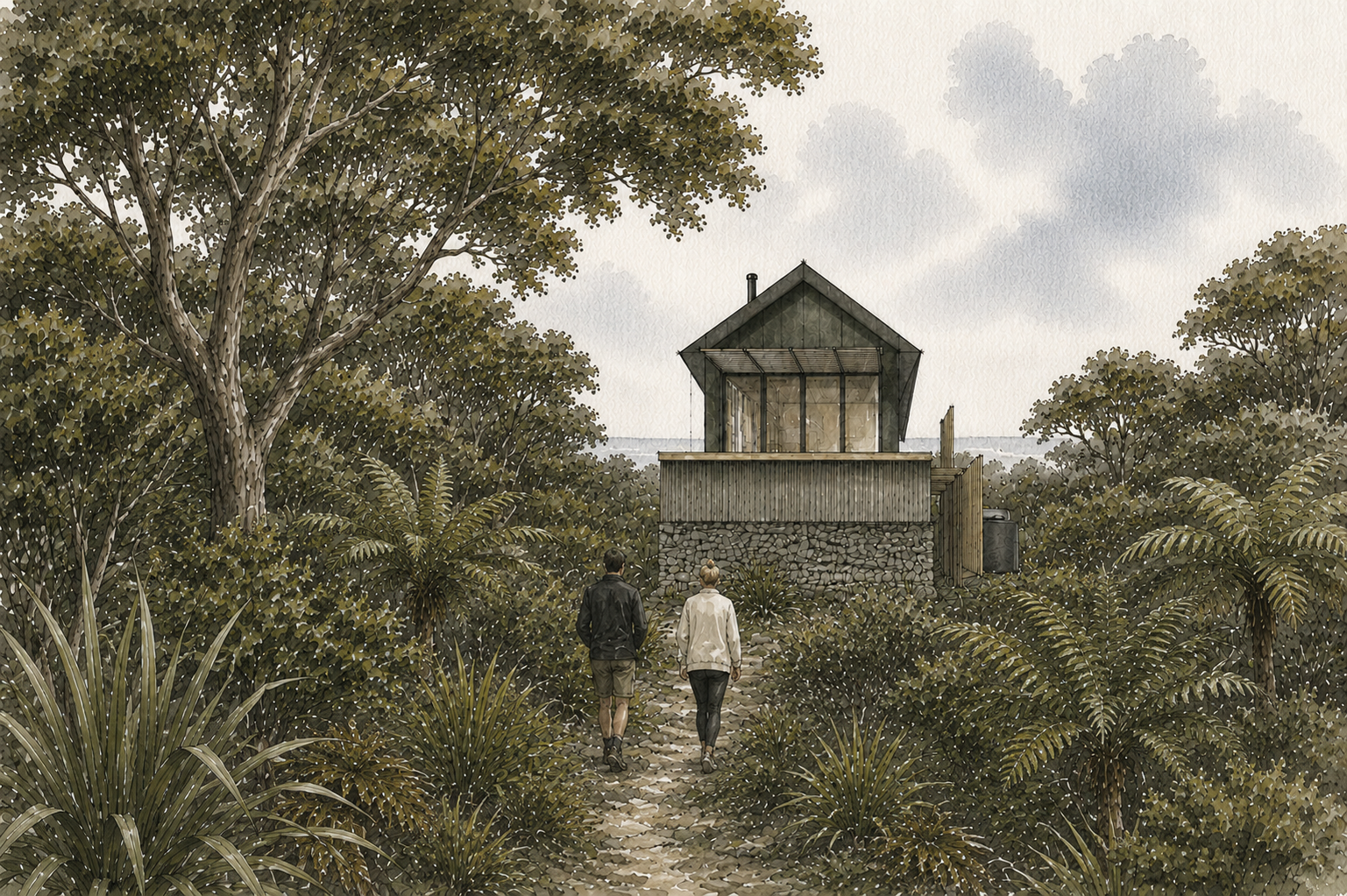 Watercolour study
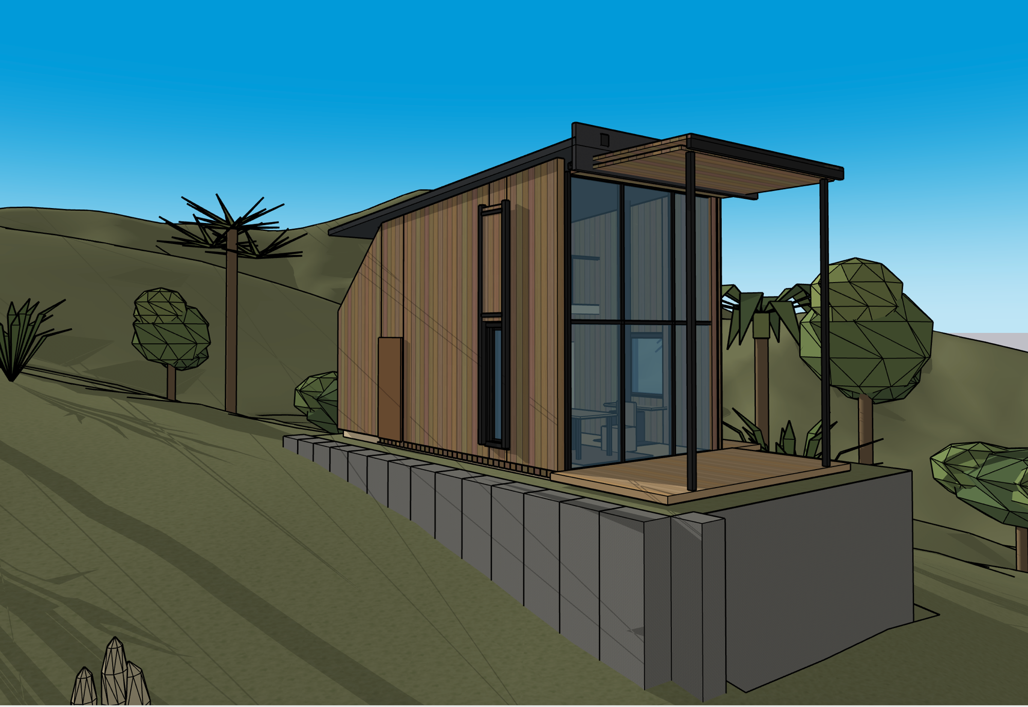 Model
Model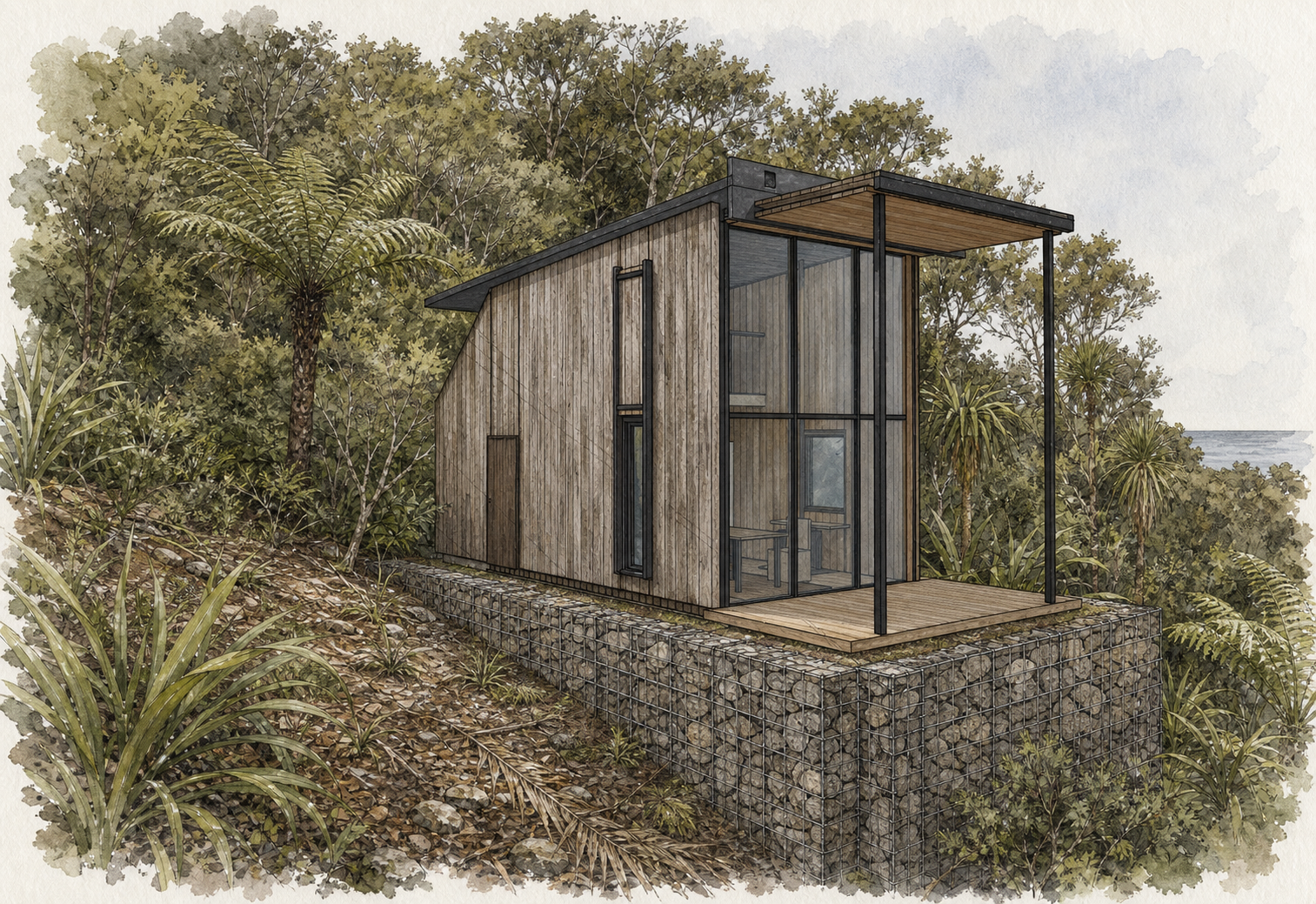 Watercolour study
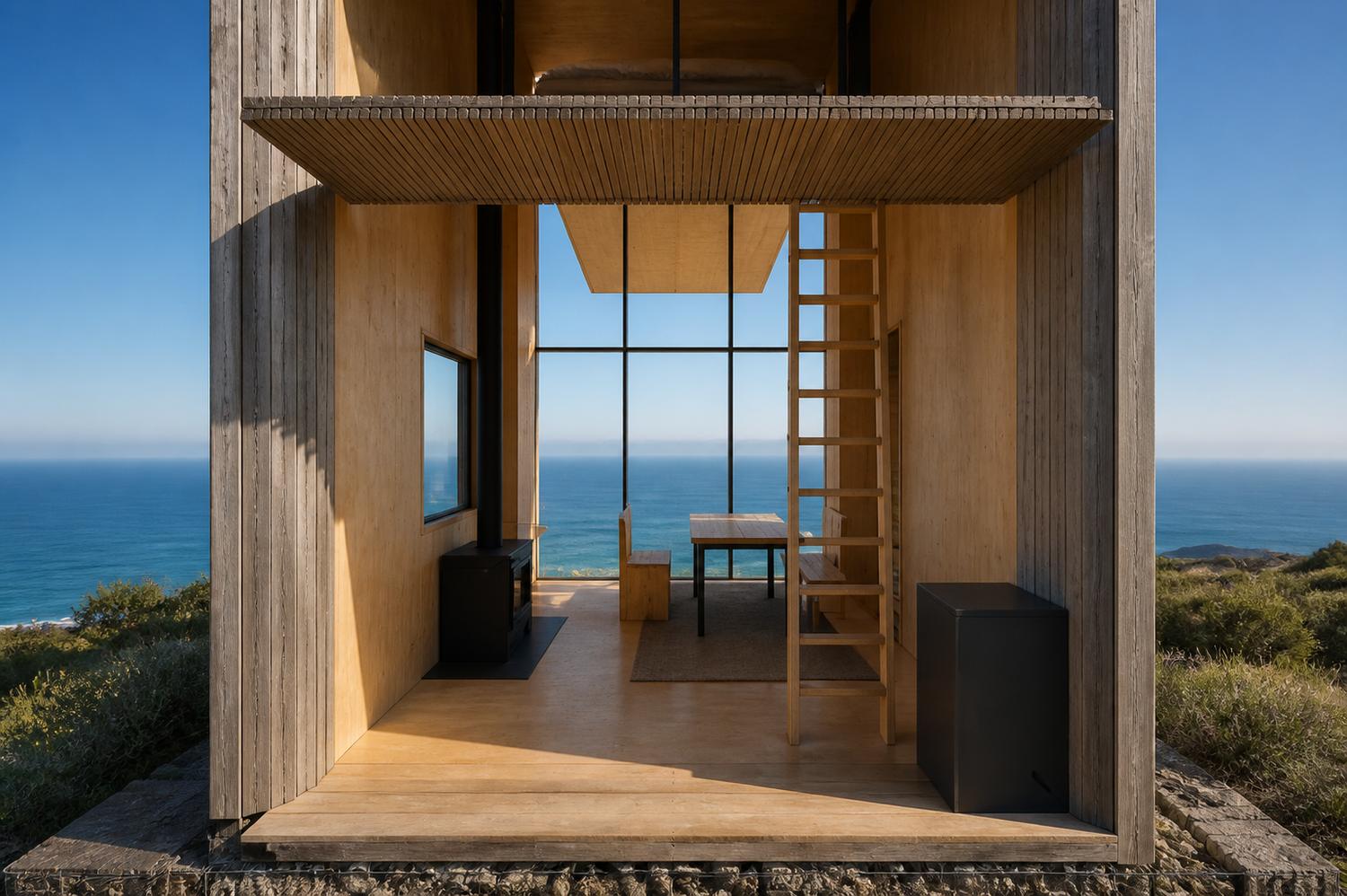
The model views became hand-drawn studies of each hut in the bush.
Figures 5 and 6 show the two directions side by side. Scheme A is the compact gabled option, drawing on the familiar character of a DOC hut. Scheme B is the taller shutter box, shown open with its front wall forming a sheltered canopy.
The model established the building and the key view. Image generation then tested how each option might feel among the ponga, flax and coastal bush. These remain atmosphere studies rather than promises of a finished building.
- Examples
- Scheme A and Scheme B
- Source
- SketchUp model views
- Outcome
- Watercolour landscape studies
- Review
- Form checked against each model
- Runtime
- 75 to 180 s per frame
The same model also supported a drawing package for specialist review.
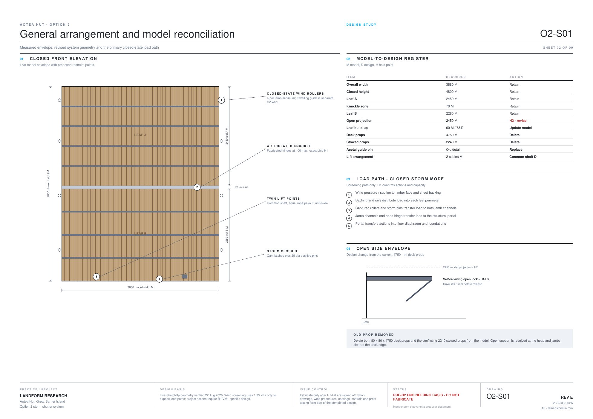
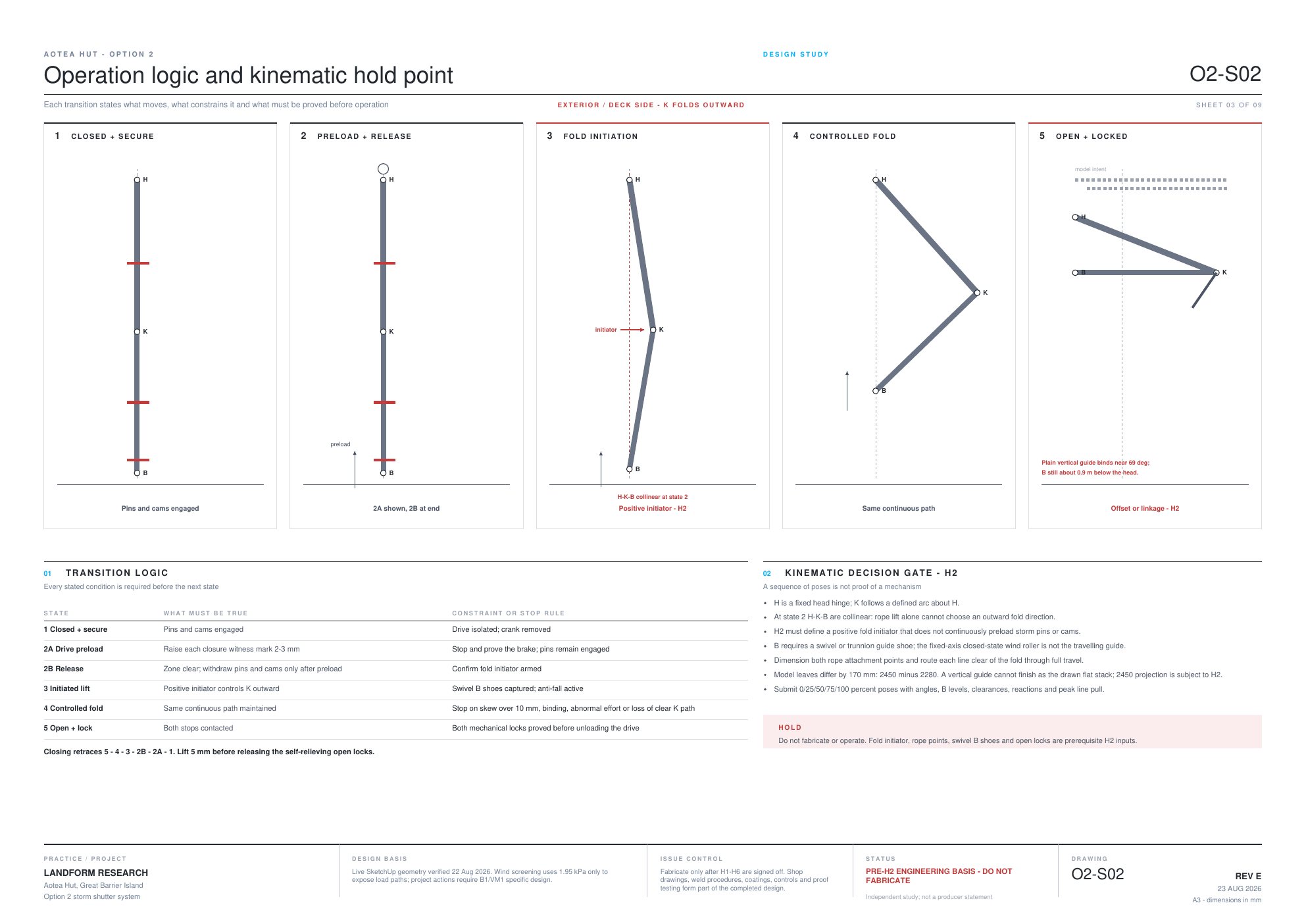
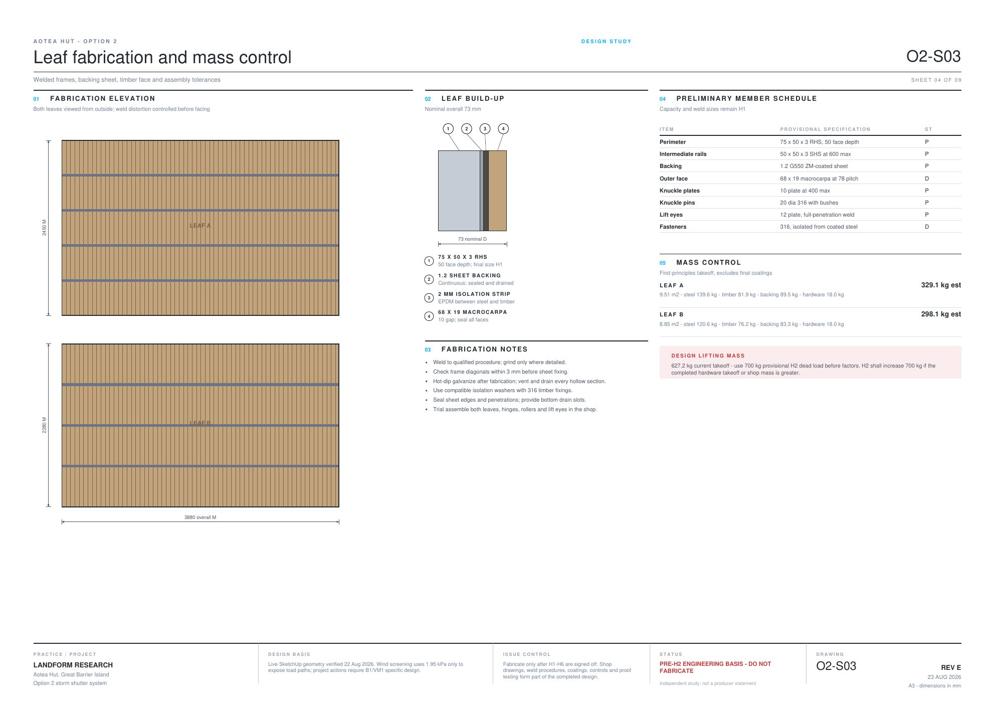
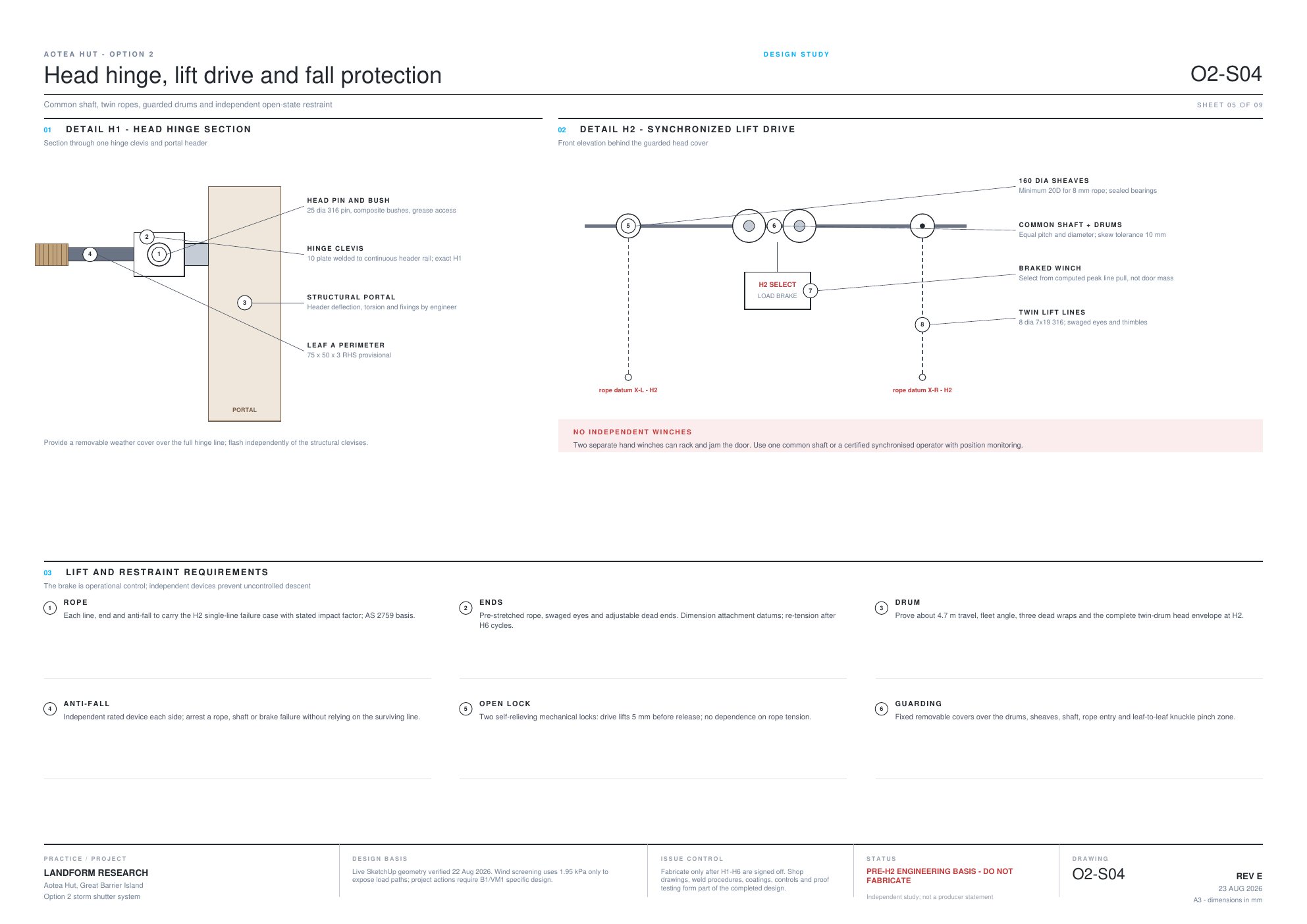
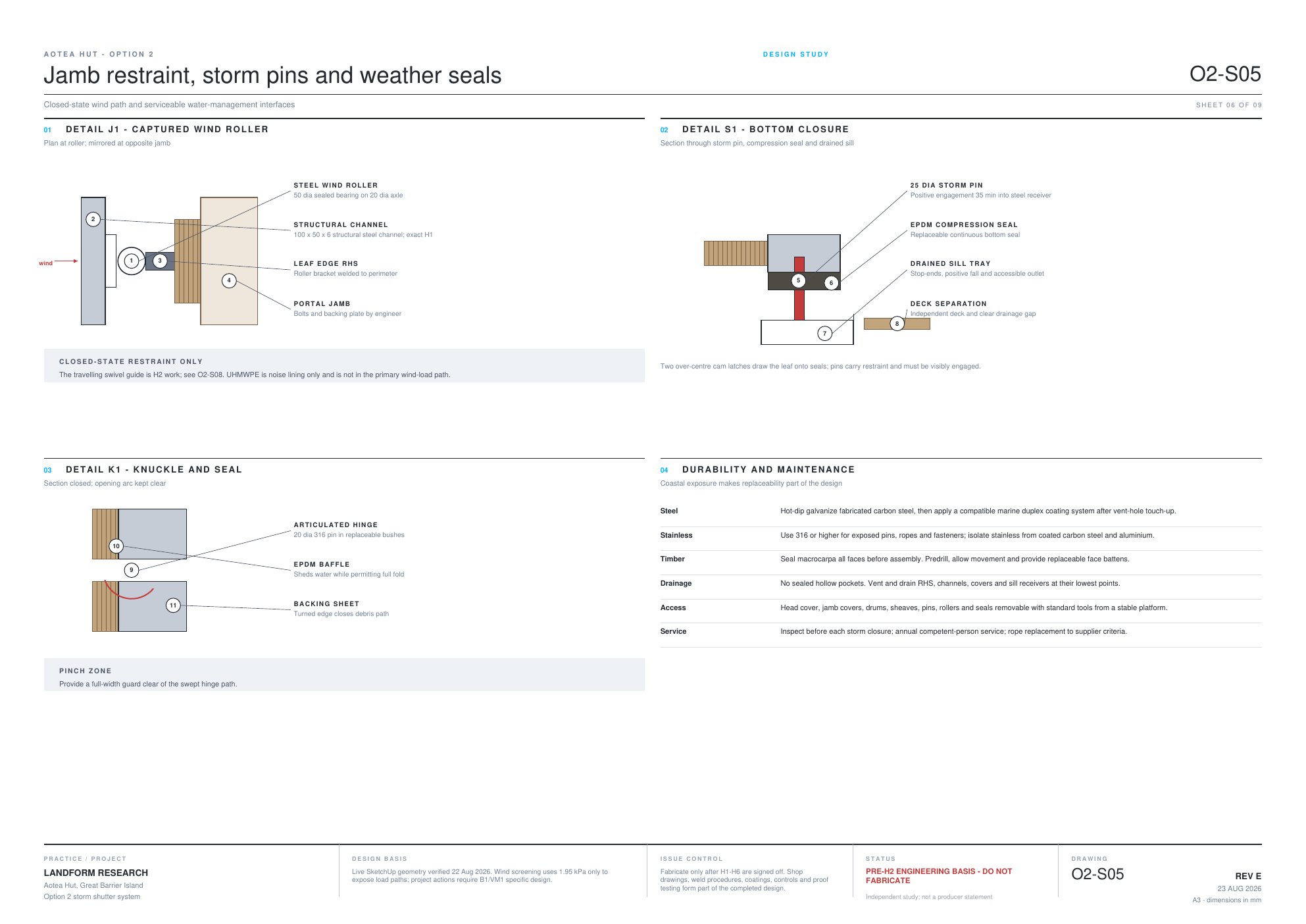
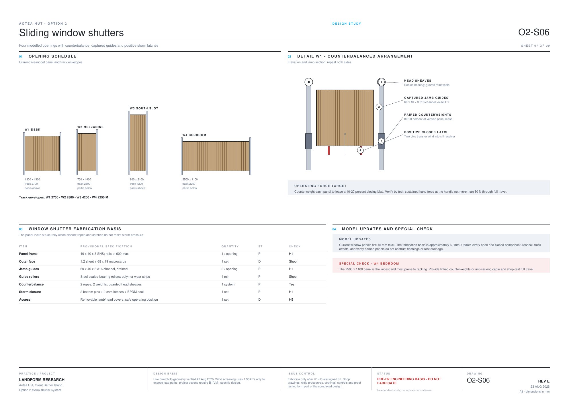
The sheets are generated as SVG at 1:5, with the conventions a builder expects: heavy outlines on cut material, hatching that names the material, dashed for hidden work, leader annotations carrying real product specifications, dimension strings, and a scale bar.
Because the sheets follow the same repeatable model, comments from an engineer or fabricator can be incorporated without redrawing every sheet by hand. The current issue is Revision E, nine sheets dated 23 August 2026, and every sheet carries the same status line: pre-H2 engineering basis, do not fabricate.
Scheme B uses one precedent idea from Hut on Sleds by Crosson Clarke Carnachan Architects: a weather-closing facade that opens to form an awning. Its siting, proportions, plan, structure, window arrangement and two-leaf mechanism were developed separately for Aotea. Crosson's shutter is a single hinged leaf; this study uses two leaves folding on a head hinge, lifted on twin lines from one common shaft. The change responds to an Extra High wind zone, where roughly 18.5 kN of screening action acts on a 9.51 m² leaf and a single leaf of that size is no longer practical to operate by hand.
- Issue
- Revision E, 23 August 2026
- Sheets
- 9, O2-S00 to O2-S08
- Format
- A3, dimensions in mm
- Basis
- NZBC B1/VM1, AS/NZS 1170, B2/AS1
- Status
- Pre-H2 engineering basis, do not fabricate
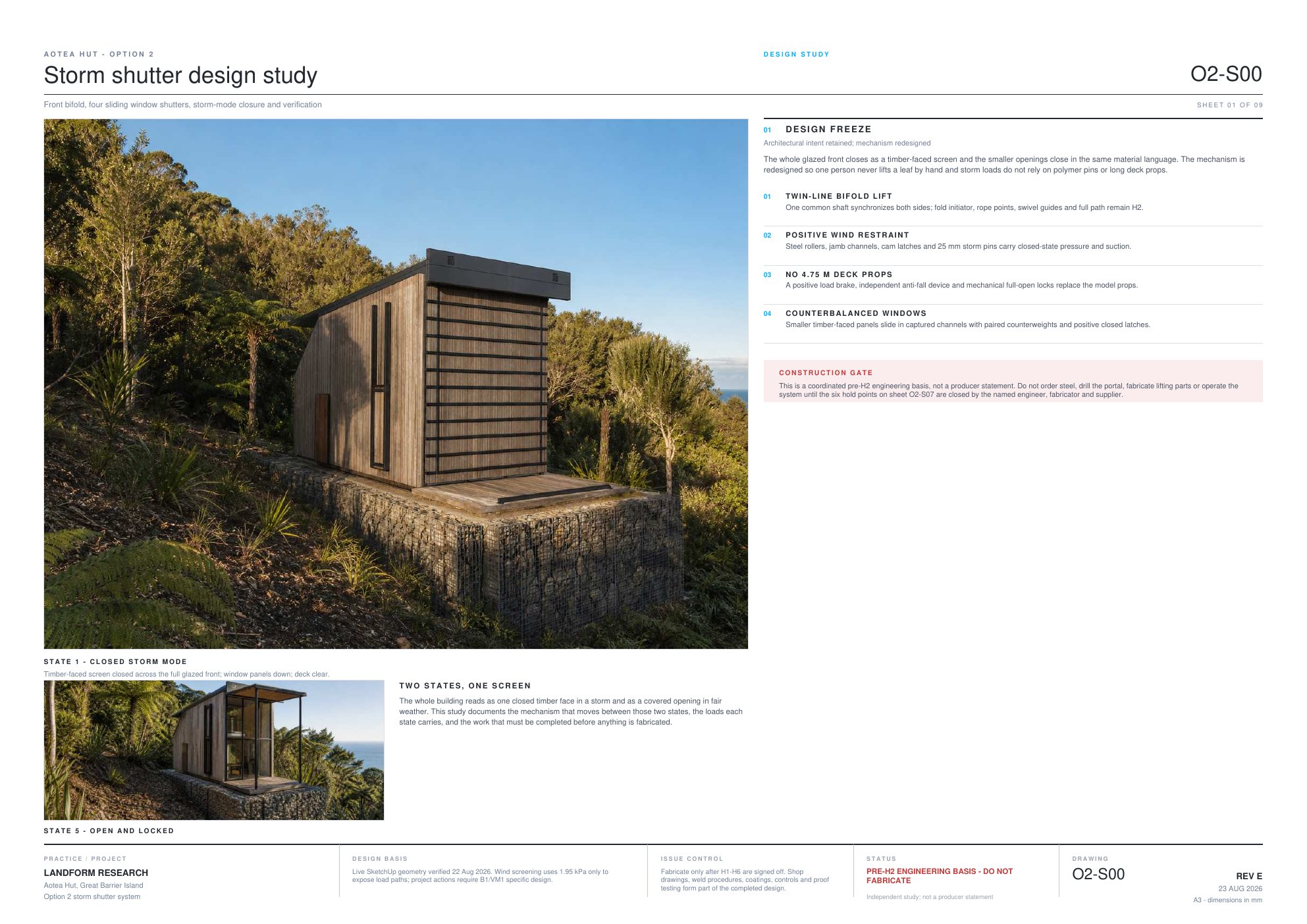
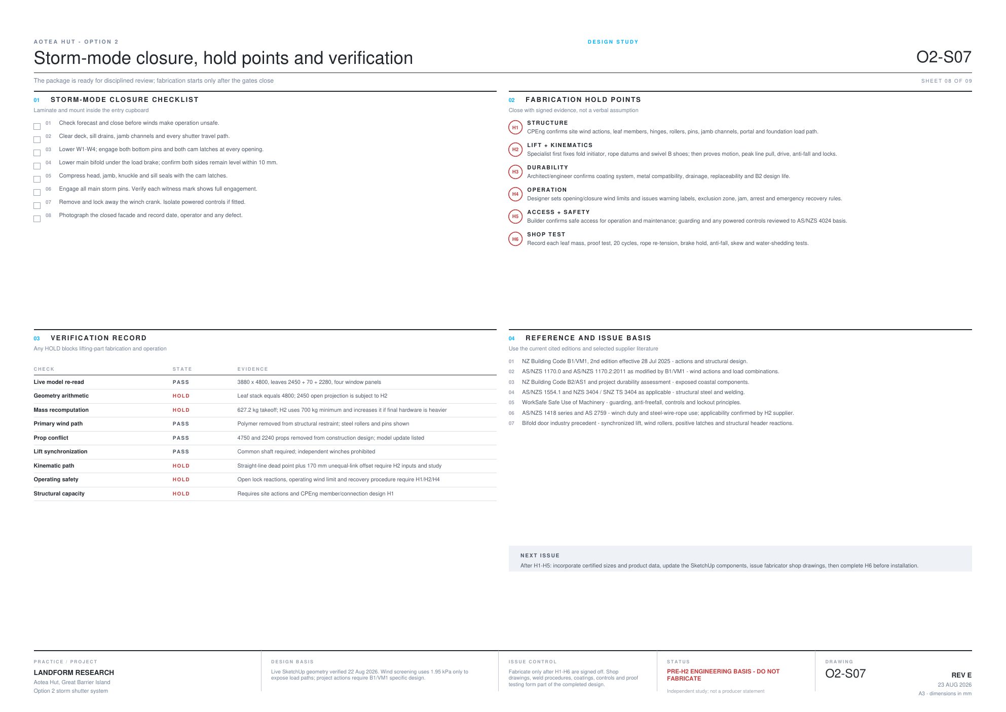
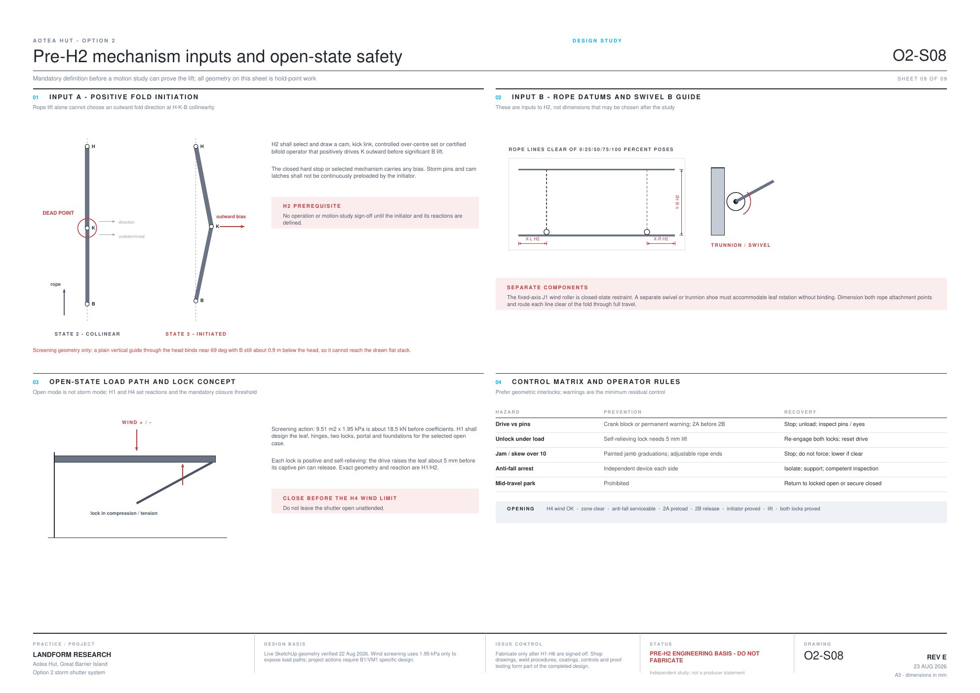
The review changed four parts of the mechanism.
Twin-line bifold lift
One common shaft synchronises both sides. Two independent hand winches can rack and jam the door, so they are prohibited.
Positive wind restraint
Steel rollers, jamb channels, cam latches and 25 mm storm pins carry closed-state pressure and suction. No polymer sits in the structural path.
No 4.75 m deck props
A positive load brake, an independent anti-fall device and mechanical full-open locks replace them. The props are deleted from the model.
Counterbalanced windows
Four timber-faced panels slide in captured channels with paired counterweights, and lock closed on two pins into a sill receiver.
Four checks have closed. Five still need specialist input.
The leaf mass is now computed at 627.2 kg, the polymer pin is out of the load path, and the props are gone. What is left is a shorter list of deeper questions.
Six fabrication hold points govern the package: structure, lift and kinematics, durability, operation, access and safety, and shop test. Nothing is ordered, drilled, fabricated or operated until all six are closed with signed evidence by the named engineer, fabricator and supplier.
Revision E, 23 August 2026. Issued as an engineering basis for review, not as a producer statement.
The early cost range shows what is known and what still needs a quote.
The early estimate uses 31 sourced rates, each with a unit, a low and high range, and a confidence note, to build staged cost views for both schemes. Freight, island labour, off-grid plant and consent fees are separate lines because on an island they behave differently from the building.
Three lines carry most of the range, and none can be settled from a desk: the access track, a barge rate that no operator publishes, and the shutter itself. The Revision E mechanism is a specialist assembly with a braked winch, anti-fall devices and a marine duplex coating, and it sits outside these thirty-one rates. The estimate carries that gap as an open line.
- Scheme A
- $183k – $401k, self-framed
- Scheme B
- $224k – $484k, self-framed
- Frame lever
- $37k – $58k, build it yourself
- Lowest confidence
- Access track, barge freight, shutter hardware
The design developed through 28 review decisions.
Each example began with me reviewing an output and deciding what needed to change. Some were design choices; others were errors or missing information. The repeatable model made it possible to respond quickly, while the direction came from review.
It looks like a house.
Scheme B exists because of thisA competent gable was rejected on character alone. The second scheme, the tall shutter box, came out of that single sentence, and out of Hut on Sleds as its precedent.
The veranda blocks the view.
Awning geometryThe shutter was propped at 70 degrees, tip at 1.5 m, straight across the eyeline. Raised to 88 degrees: a flat canopy at 2.24 m.
Where do the poles go when it is closed?
Mechanism resolvedThe props had no stowed state. They became pivot shoes that fold flat into deck clips. Revision E then deleted them outright: a load brake and two mechanical open locks do the work instead.
I should see into the house, not onto timber.
Real openingsWindows had been glazed in front of a solid wall. Every wall was rebuilt as segments around its openings.
Some of the trees are floating.
Placement rewrittenRaycasts had been hitting canopies. Heights now come from the elevation model directly, for all 35 plants.
There are no measurements on this.
Details became drawingsThe first detail sheets were annotated pictures. Dimension strings, then a jamb detail, then an operation sequence followed.
Five early problems changed the way the workflow was built.
The model was 25.4× too large
The API measures in inches; the builders write millimetres. Every view was internally consistent, so nothing looked wrong until something was measured.
Cutting openings deleted walls
A push-pull through a wall silently removed it. Walls are now assembled as segments around each opening, which cannot fail the same way.
Objects floated above the ground
Raycasts hit canopy and roofs instead of terrain. Twice fixed by hand, then fixed properly by reading the elevation model.
Interiors rendered black
The physically-based path needed a lighting rig nobody was going to build. The whole approach was replaced.
A render lost the bath
Generated images drop things they consider unimportant. Each generated frame now receives a visual check against the model.
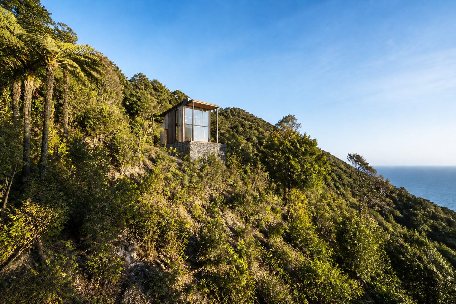
AI made a detailed early study practical before committing to the next stage.
In about four hours, the study produced a siting rationale, two schemes, a shutter concept developed far enough for an engineer to identify what is still missing, and a cost range with its uncertainty named. The siting and the first scheme took under an hour; most of the rest went into the details, the images and this page.
This remains a concept study. I made the decisions about the site, the preferred scheme and the shutter direction. A site visit and advice from a planner, geotechnical engineer and structural engineer would be needed before the project moved further.
- Standing
- Concept design, no consent set, no engineering
- Still required
- A site visit
- Sufficient for
- Deciding whether to keep going
- Open
- Five checks, six fabrication hold points
- Next
- Access, planner, geotech, CPEng
The study was also prepared as a book and a short walkthrough.
This page is the method. The same work is also set as a 28 page volume you turn by hand, and as a ten second walkthrough generated from the model camera. A separate note compares all three and considers when each one might help a client or colleague understand the work.
Open the note volume, walkthrough, page- Volume
- Field Notes Vol. 01, 28 pages
- Walkthrough
- 10 s, from the model camera
- Page
- This study